ElGuano
Well-Known Member
- Thread starter
- #1
I've been thinking about the idea of a GMRS radio in the cab for a while now, and have been slowly accumulating plans and parts til now. Everything came together last week and this weekend, and I've just finished up the most extensive interior/exterior mod I'll probably make to my Rivian. Many thanks to the early trailblazers here who have set the path, including @spamurai , @Ervan, @alanjohnwilliams and @Joules Burn. I never would have attempted this if I didn't feel completely comfortable with the disassembly and modification steps.
Summary
I installed a Midland MXT575 50-watt GMRS radio on my 2025 R1T TriMax. TheThe "headless" head-unit is hidden inside the passenger dash, with a microphone/control jack added to the bottom dash where the cab 12v socket used to be included. Power and antenna pass through a grommet in the firewall, where I tapped a 12V power source (directly linked to battery). The antenna cable is tucked along the edge of the windshield/A-pillar up to the roof, where I have a custom bracket holding an NMO mount on the eyelet intended for the Rivian crossbars. My main objectives for this build were reverseability (I can easily move the antenna mount to the back crossbar eyelets if I ever need the roof crossbars) and professional appearance, with minimal exposed cables, no awkward tucking in between trim pieces, etc.
Parts and Supplies
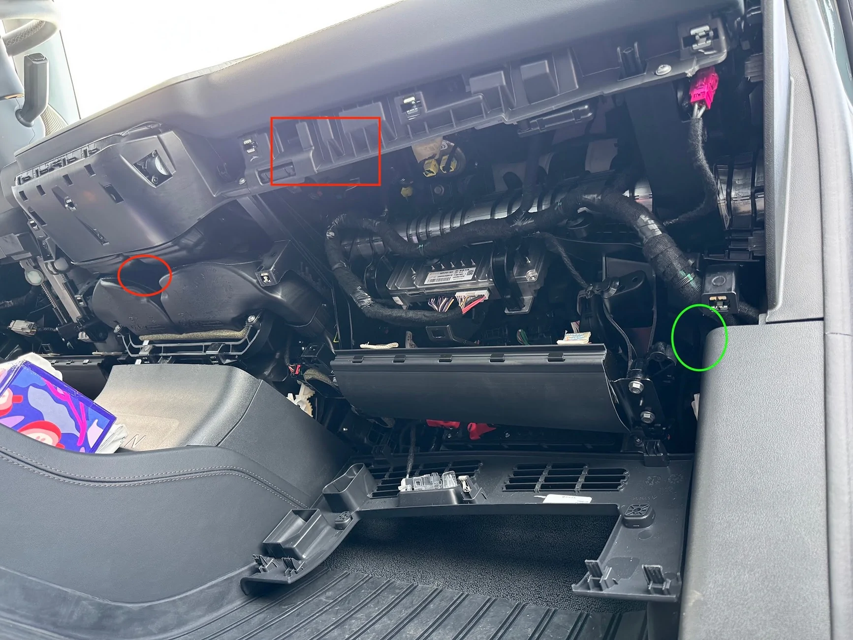
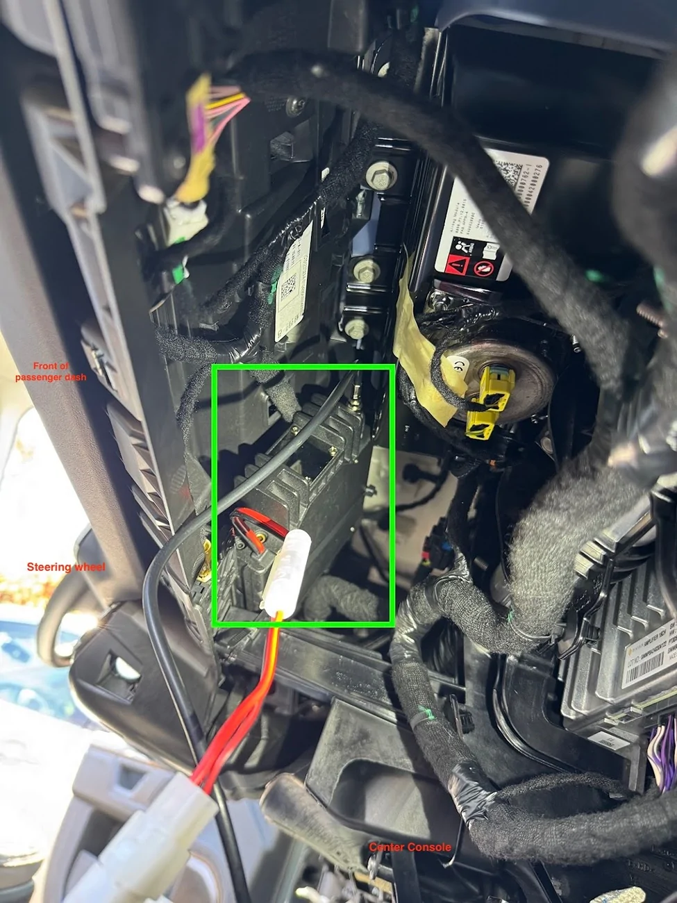
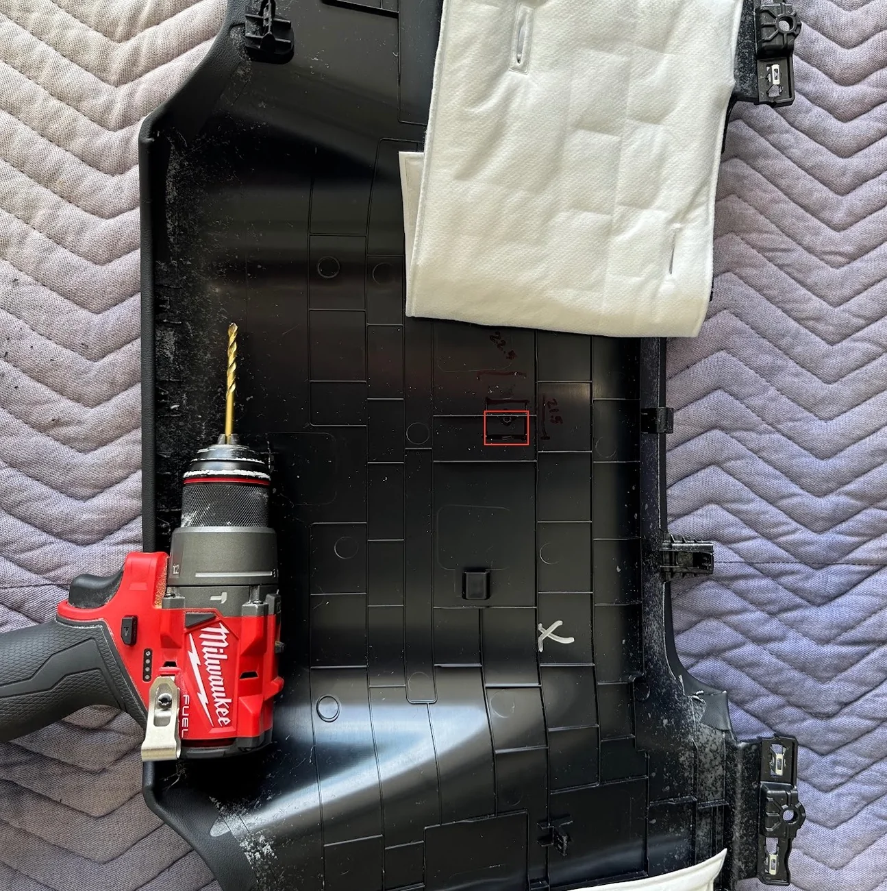
I first considered whether to install the headunit in the frunk/engine bay, in the gear tunnel, in the rear seat storage, or inside the dash. Each had its own complications and wiring/routing challenges. Ultimately I decided to put it in the dash, and route power and antenna cables to the engine bay. Here's the overview pic. Front passenger footwell looking up towards the front of the truck. The red square is where the headunit is tucked. The red circle is where the RJ45 female port is installed for the mic. The green circle is the location of the grommet to fish cables from:

First, I removed the lower passenger footwell panel. There are 5 clips that just pull/pry out, no screws on this side.
The flexible panel cradled by the U is the passenger knee airbag. Do not touch or mess with that in any way.
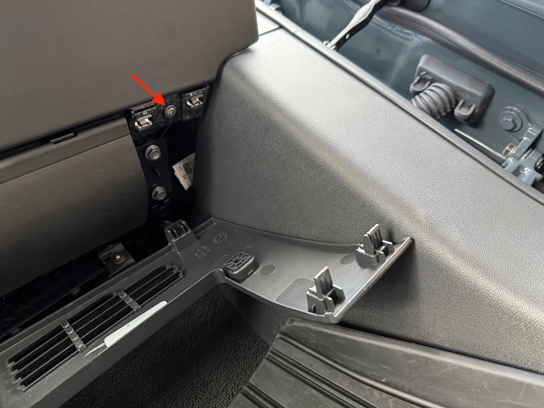
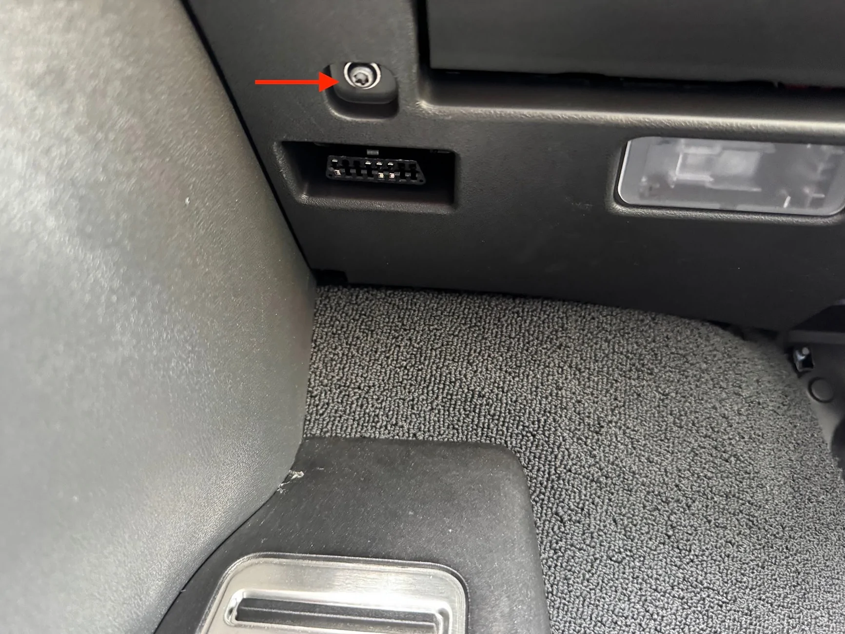
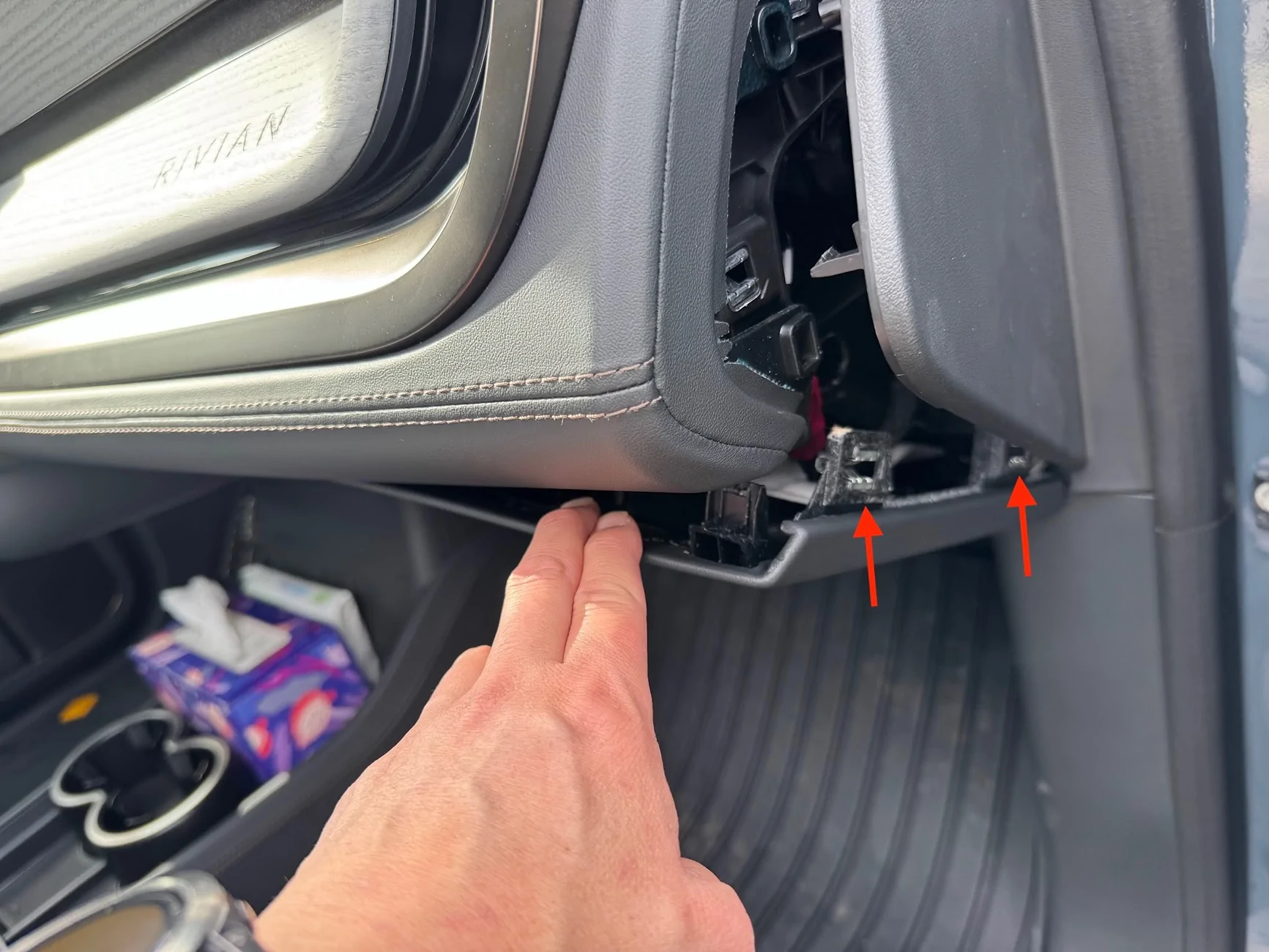
This exposes two T-25 torx-bit screws that I needed to remove in order to remove the full-length under-dash panel that spans the driver and passenger sides. The first pic is one near the center console, the second is near the passenger side door:
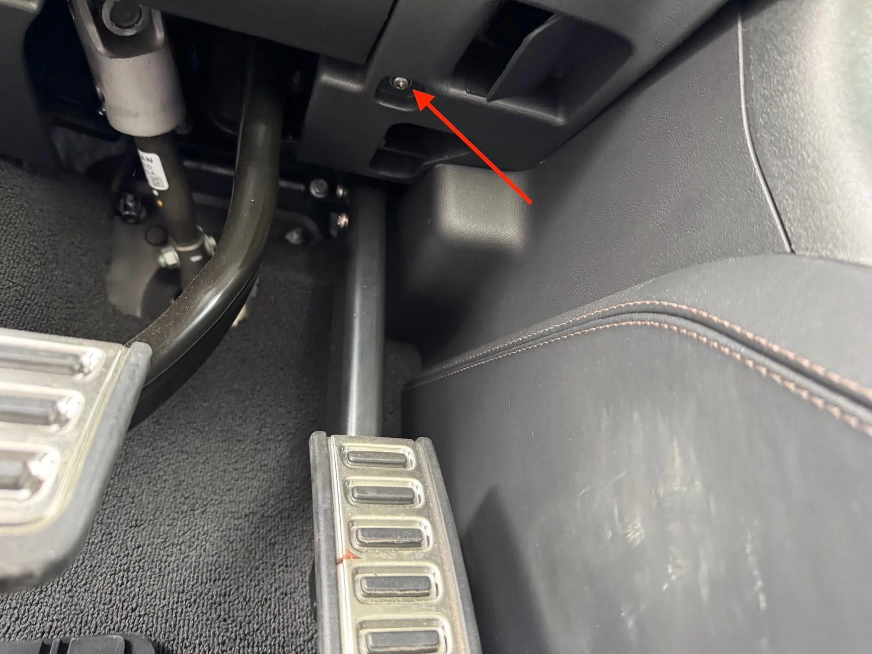
While I was at it, I had to do the driver side too. NOTE that on my car, the driver side has two additional T-25 torx screws that had to be removed first. So this makes for a total of 6 torx screws between driver and passenger side. The driver side is actually two pieces. The small piece above the accelerator will come right off. The clutch side just needs to be loosened to access the hidden torx screw (just like on the passenger side):
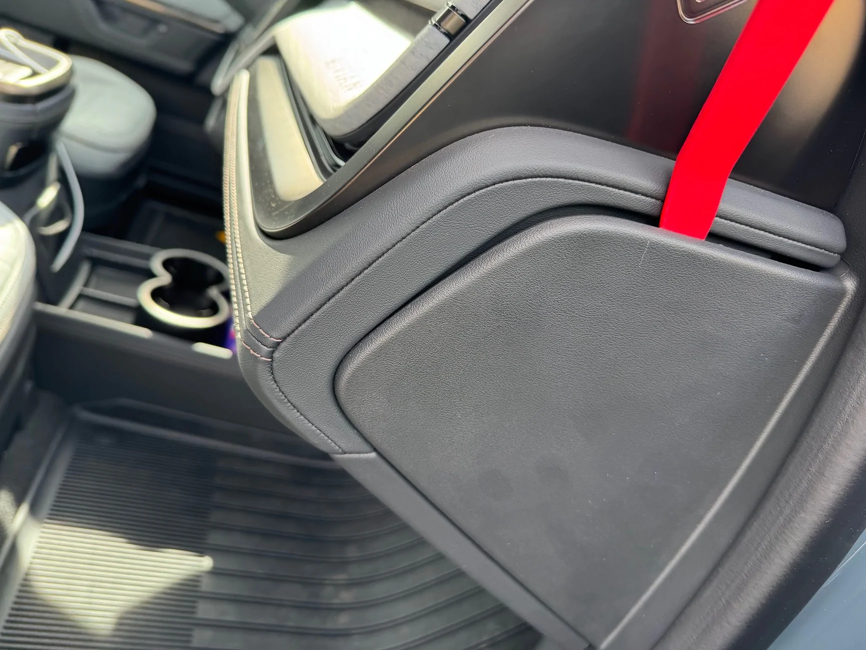
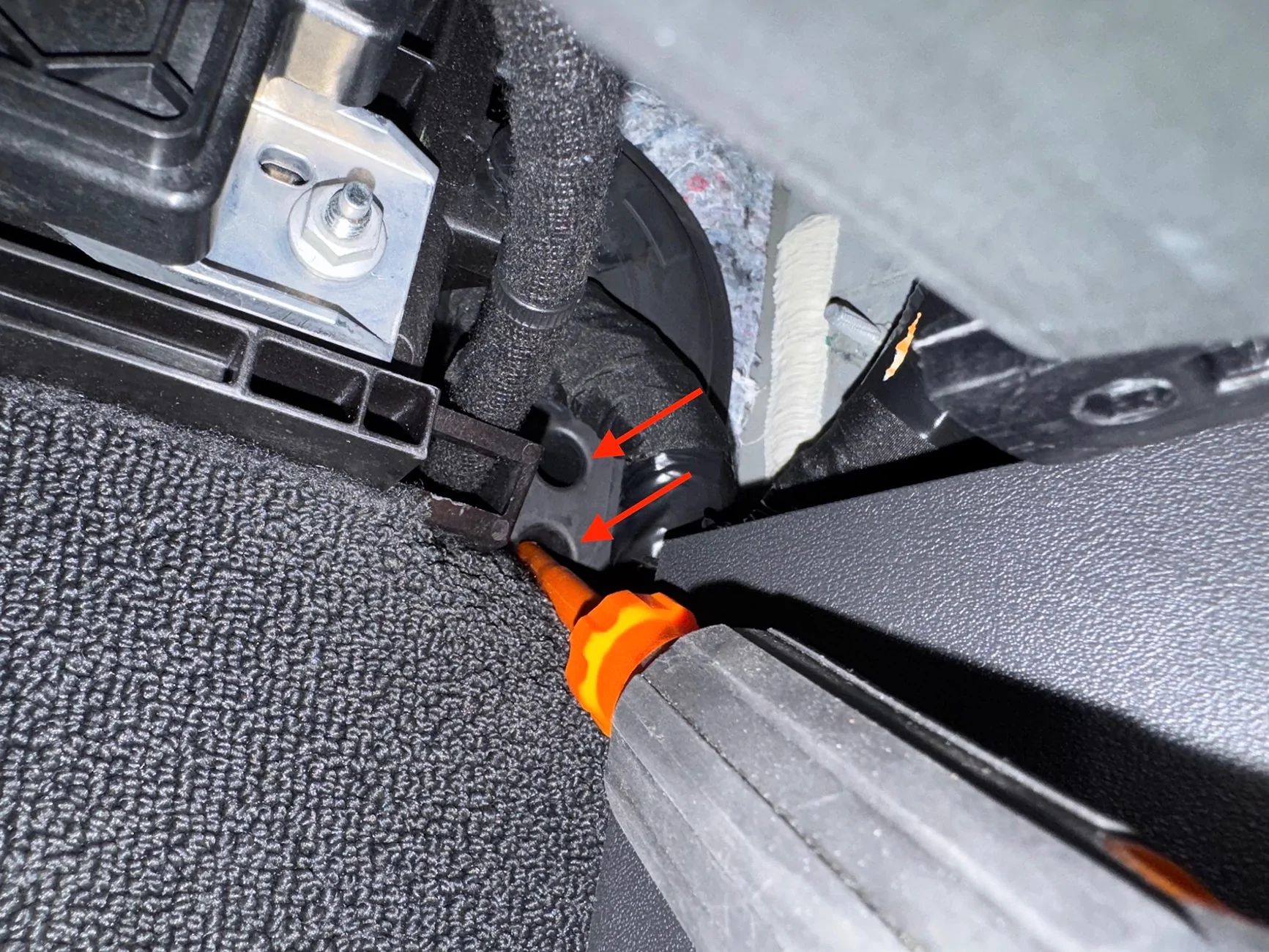
Before removing the under-dash panel, I had to pop and loosen the small side panel that is exposed when the the front door is open. The lowest two clips anchor the dash piece; I didn't need to remove the entire side panel:
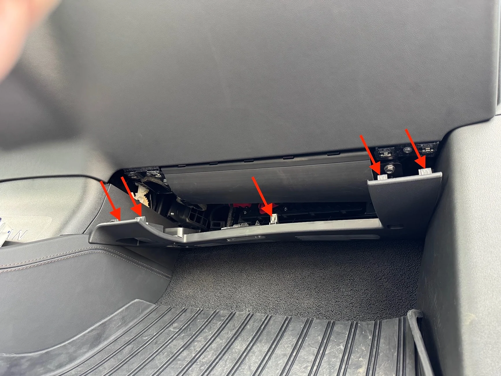
I had to do the same on the driver side to get the full panel off, which is needed to cut the hole for the mic adapter. I started pulling the panel down by releasing the clips:
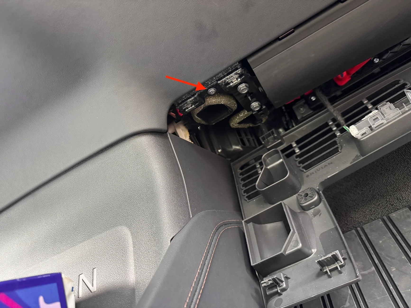
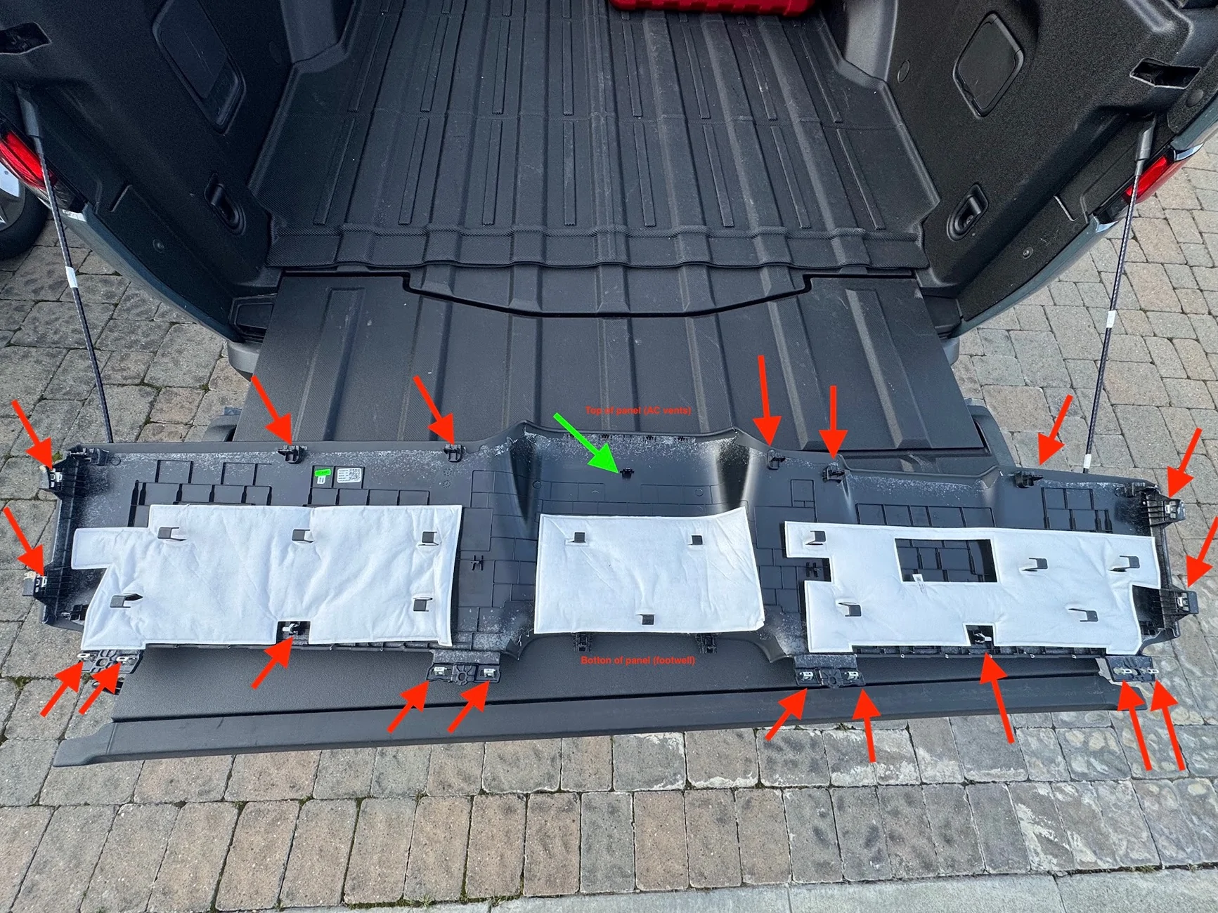
Here are the clip locations. The center area is by far the most troublesome. The green clip took a LOT of force to remove, and it pulled a metal barb out of the retaining clip that I had to reseat. The two protrusions at the bottom need to be sandwiched to the center console back (the piece with the big RIVIAN letters on it). The AC vent shroud area at the top has to be carefully removed from the vents, which have all kinds of sharp shark-teeth that will scratch and cut the faux leather.
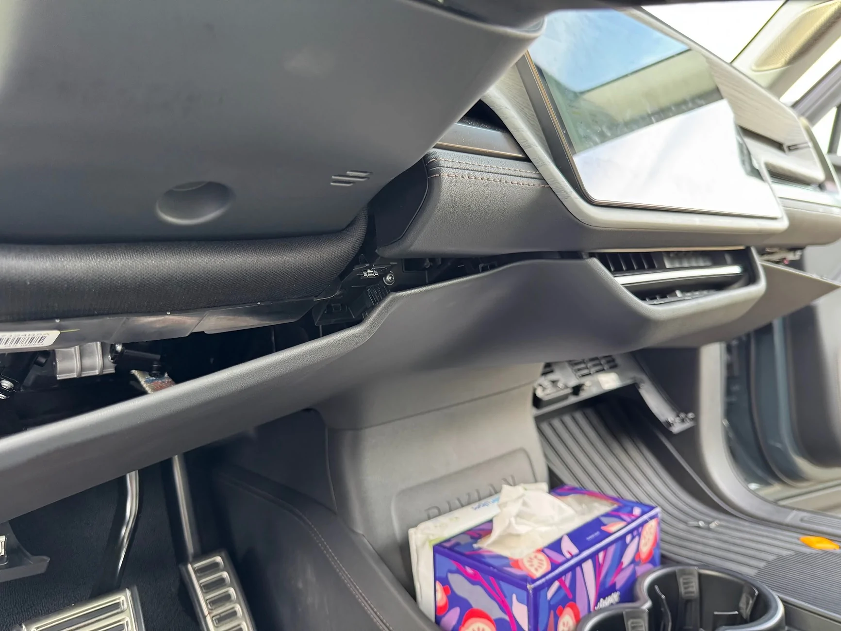
Once the panel is off, this is what I was left with:
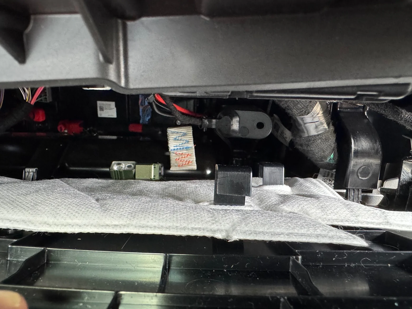
There are a few mounting positions available. The MXT575 is a big unit, and some of the smaller ones can fit almost anywhere. I followed Sulley's approach and placed in the passenger dash closer to the center display, on a ledge/perch that it can stand up sideways on, and it's safely sandwiched between support members, with the mic facing outward. Here's a picture from the bottom of the passenger footwell by the door, looking up towards the driver-side ceiling. The radio headunit is in green.

I used industrial-strength velcro and zip ties to keep the head-unit there. Hopefully it'll be stable enough. One thing's for sure, it's super loud even at volume 3-10 in this location.
12V Power Cable
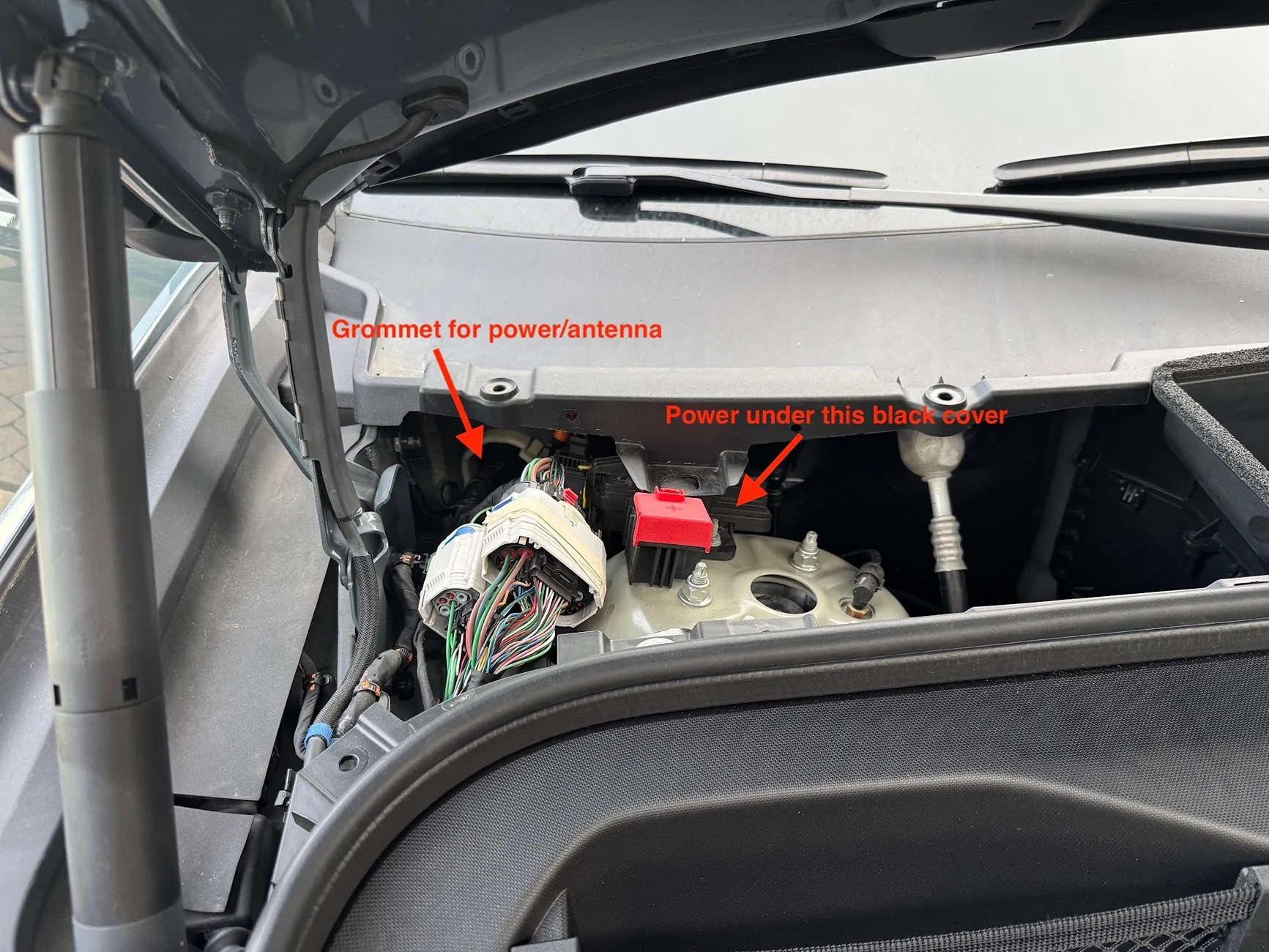
Moving on to power and cable routing next. First, I popped off the trim piece at the back of the frunk, it just comes right off with a few clips:
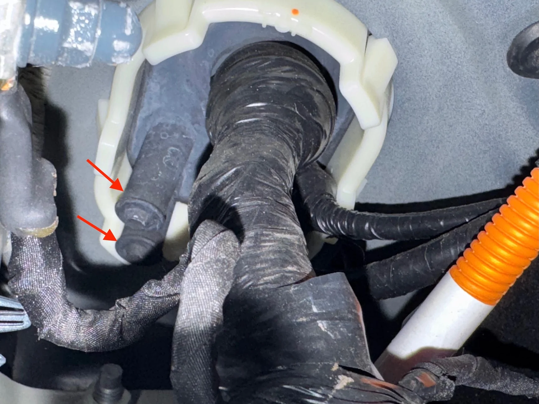
First, the grommet. A closeup of the above picture shows the two exposed/unused nipples that can be cut/pierce to pull wire through:
Here it is from inside the cab, at the back of the passenger footwell near the door hinge side. It's a fit for a hand, so I'm using a screwdriver to just puncture the nipple from the inside. Hint - use grease/lubricant, the grommet is very tacky/sticky rubber.
Unlike others have found, on my car the grommet is VERY stretchy, it's like a thick balloon. I had to use a longer screwdriver to puncture it, and when pulling the screwdriver out, it pulled the nipple and er....prolapsed it. Which is actually great, because the antenna has to be fished from the outside in, and for me, the power from the inside out, so having one nipple outward facing and one inward facing worked out great. Here you can see from the engine bay, the flathead screwdriver breaking through the grommet:
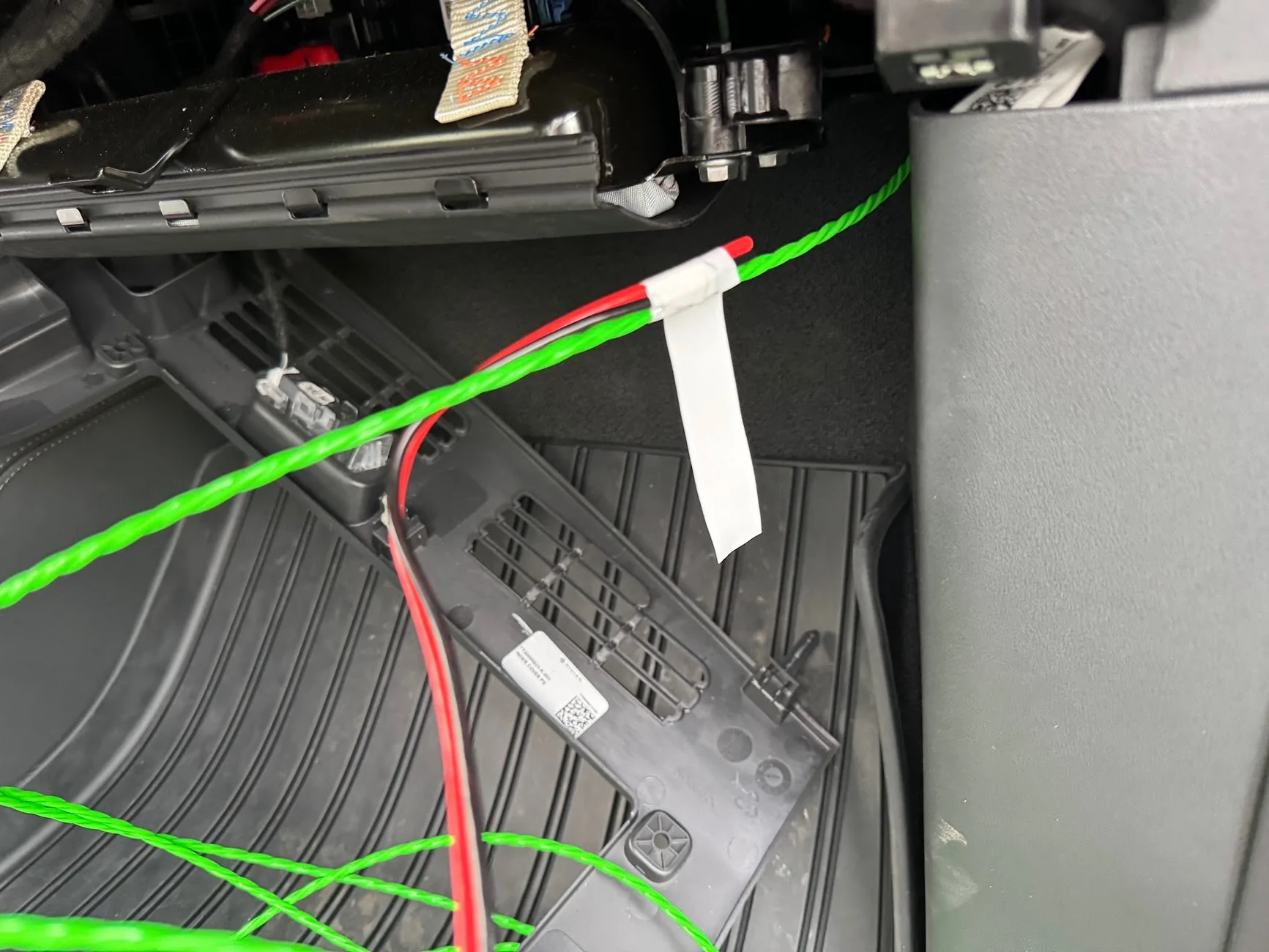
I used a bit of grease on the grommet, then stuck a fish tape wire from the inside and just pushed it through:
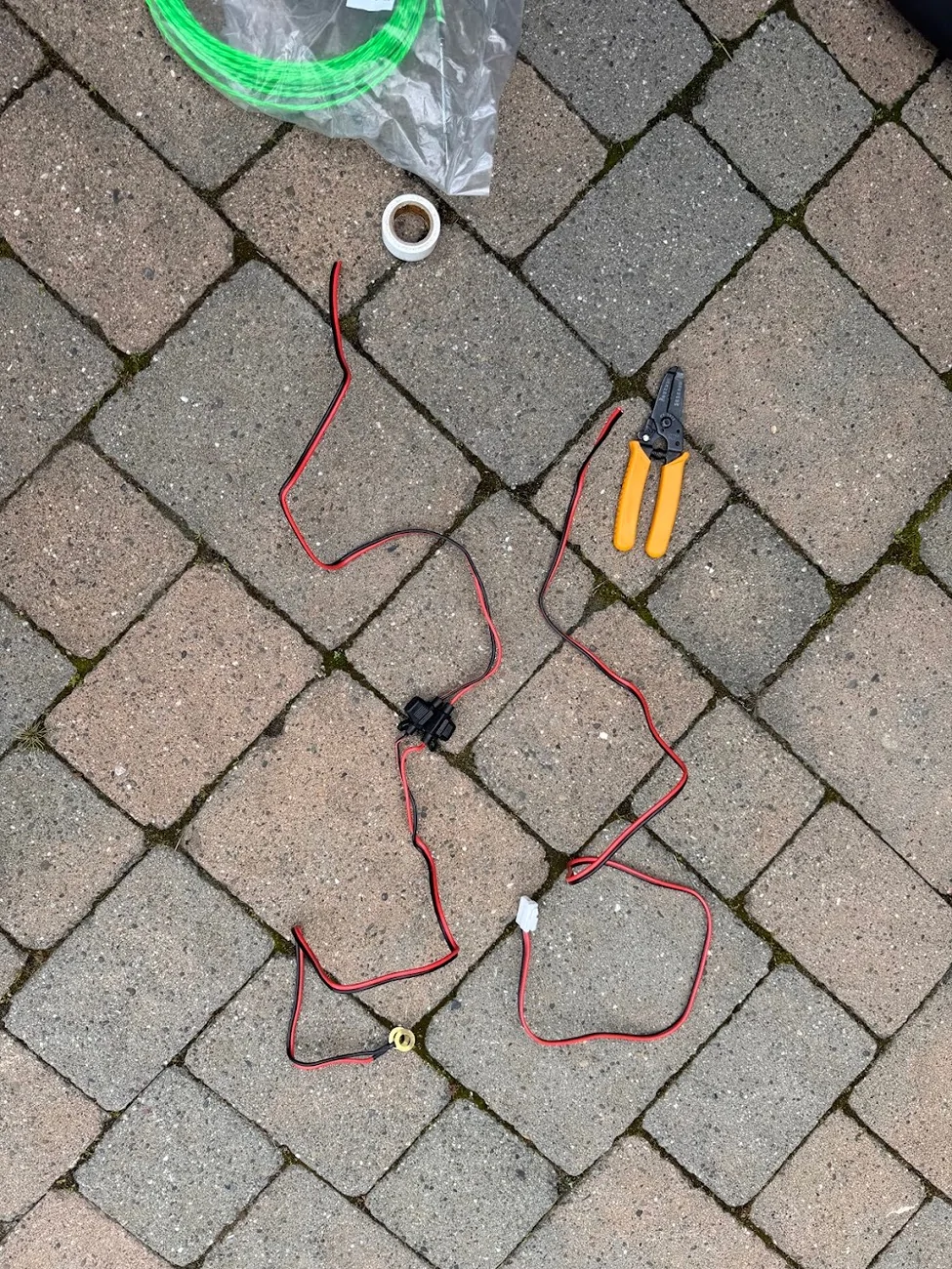
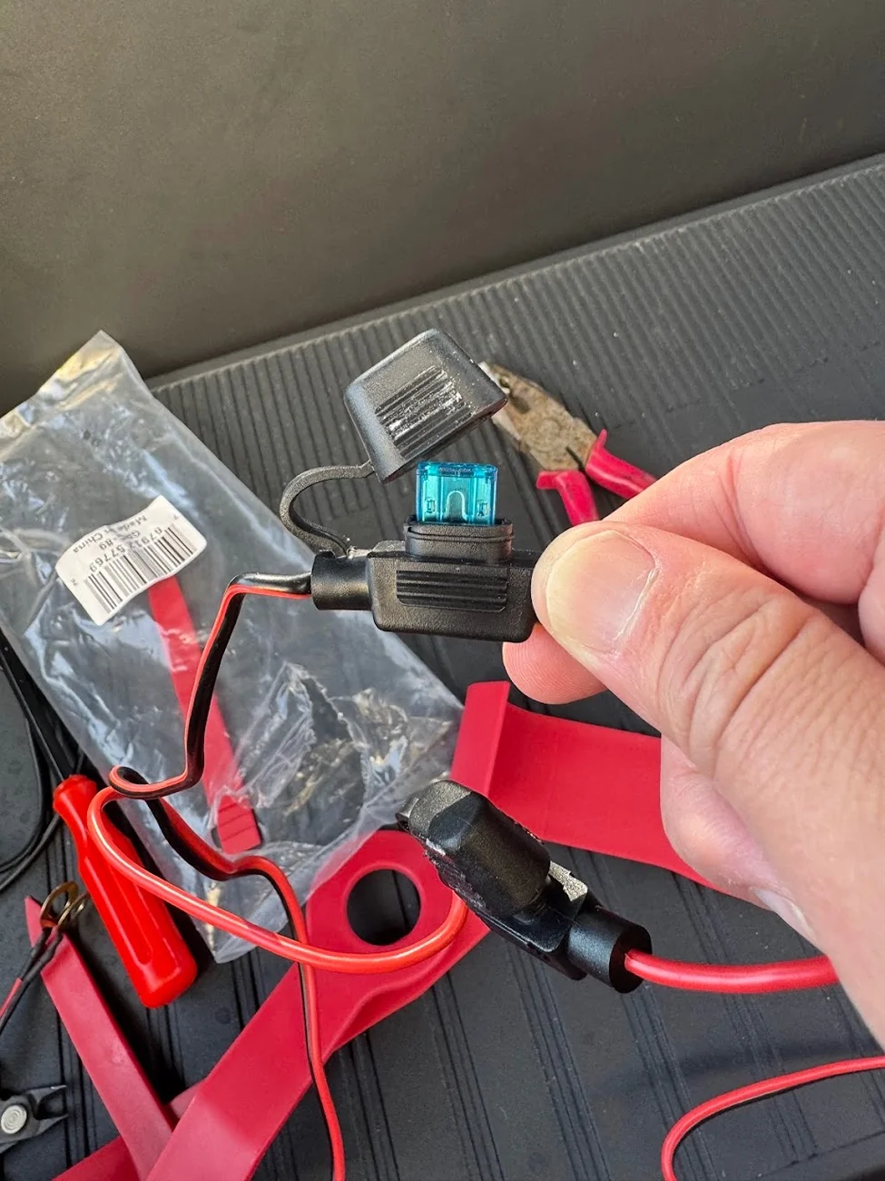
The power cable for the radio has all kinds of weird connector ends, as well as fuses in the middle, so I had to cut it to fish through the grommet.
I taped the segment of the power cable to the inside and just kept fishing the wire through. Once I got the power cable through, I just removed the tape and pulled out the fish tape.
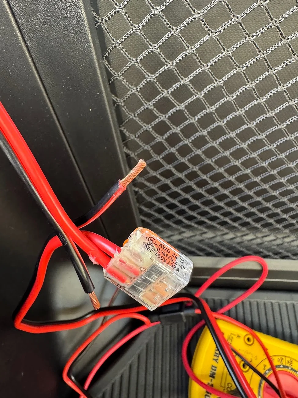
Once through, I reconnected the two segments of the power cord with a WAGO lever nut for each of the 12v and ground wires. I used 3-lever WAGOs in case I ever wanted to tap more 12v power (e.g., frunk outlet). I also packed the wagos with waterproof grease and wrapped them in electrical tape, then zip-tied them face-up so any water runs down them and not into them. LMK if I'm going to burn down the car.
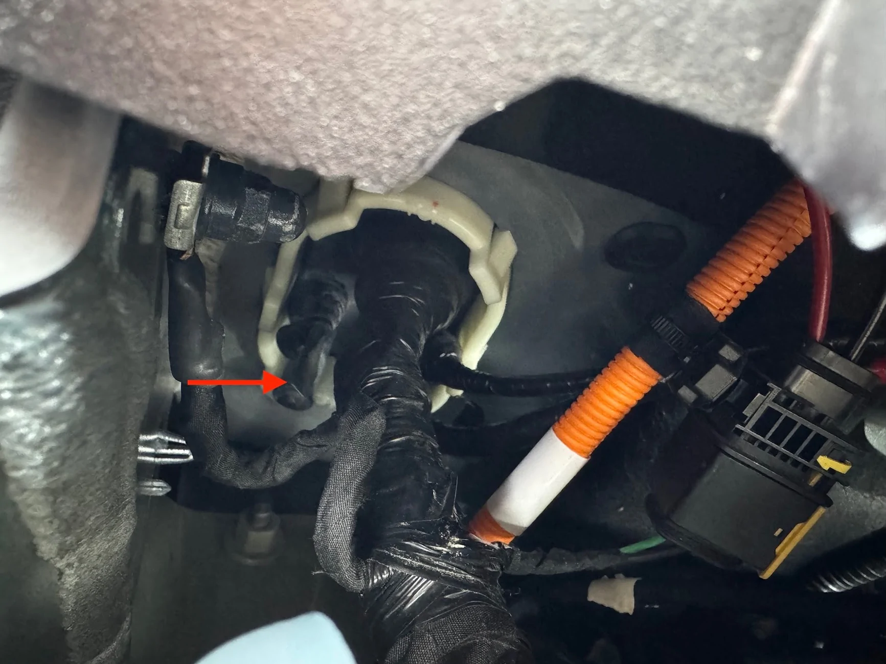
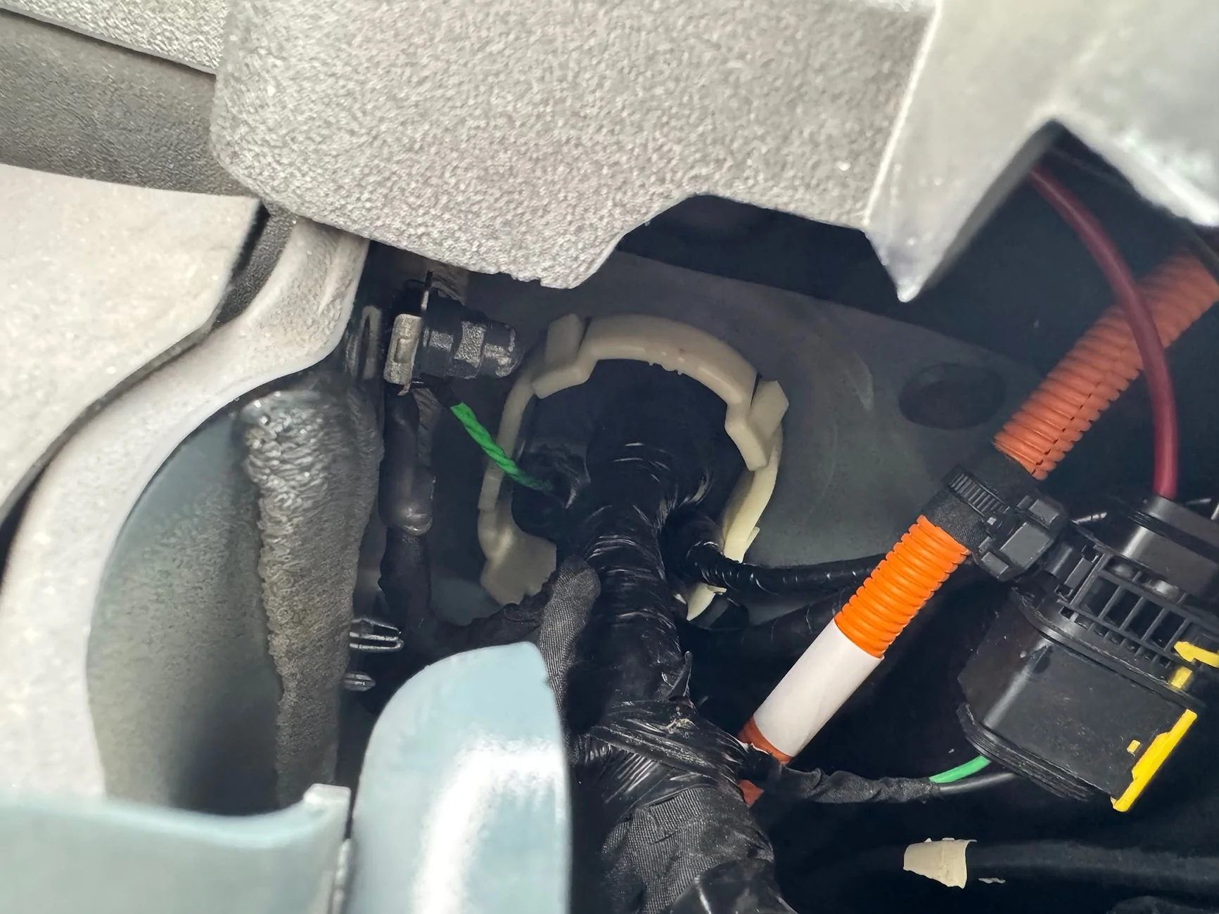
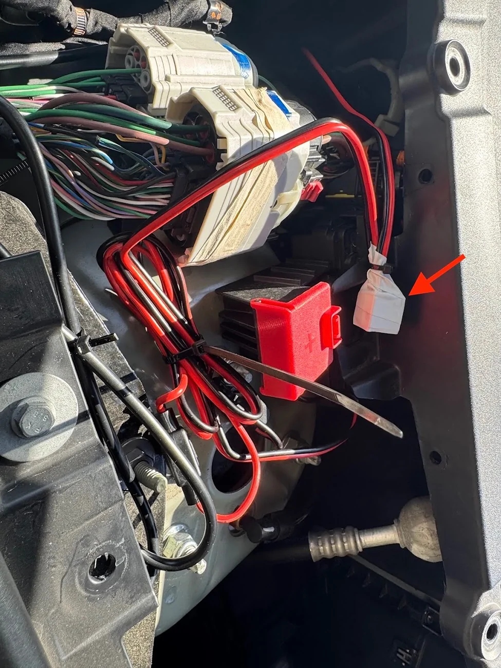
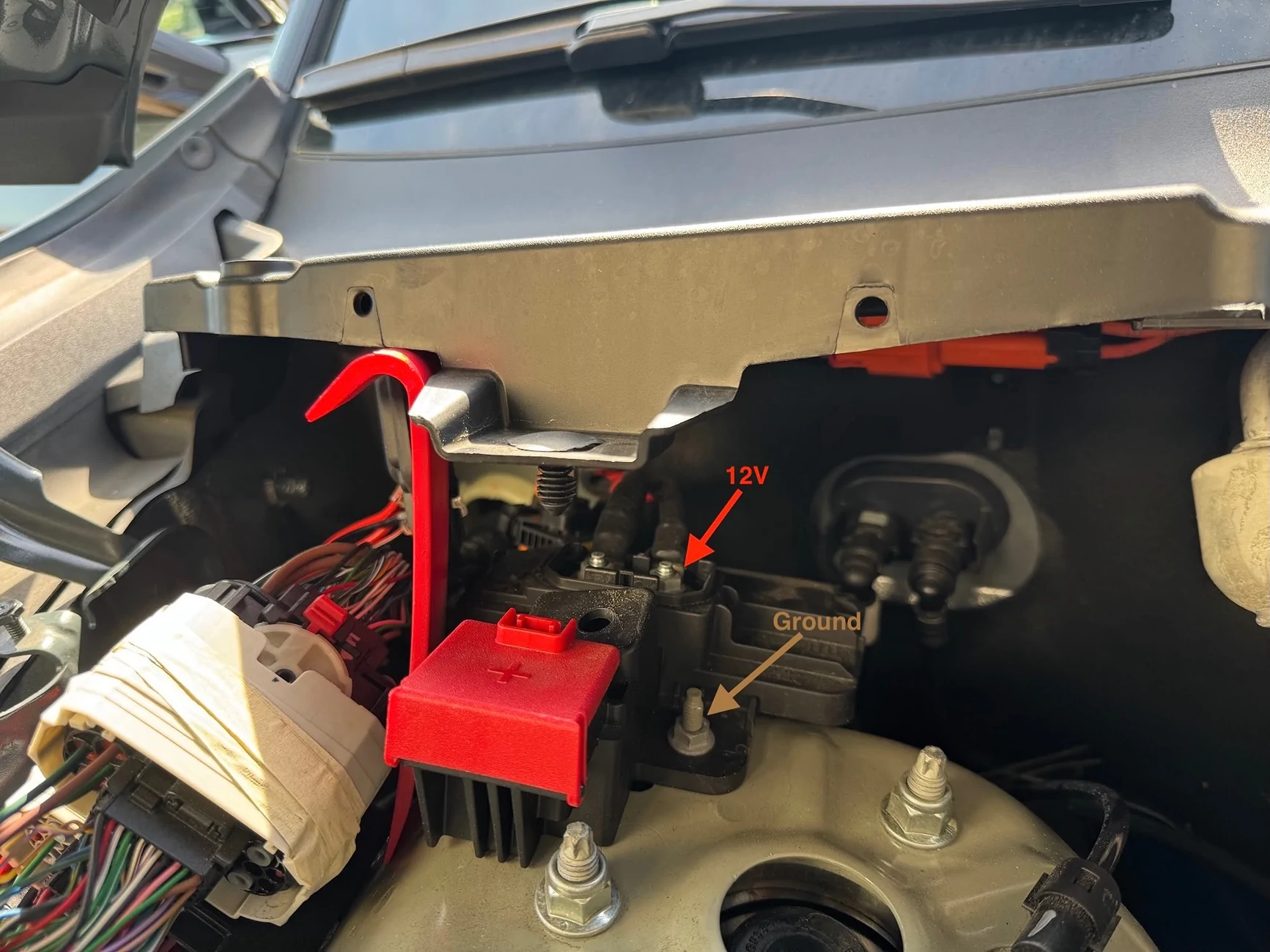
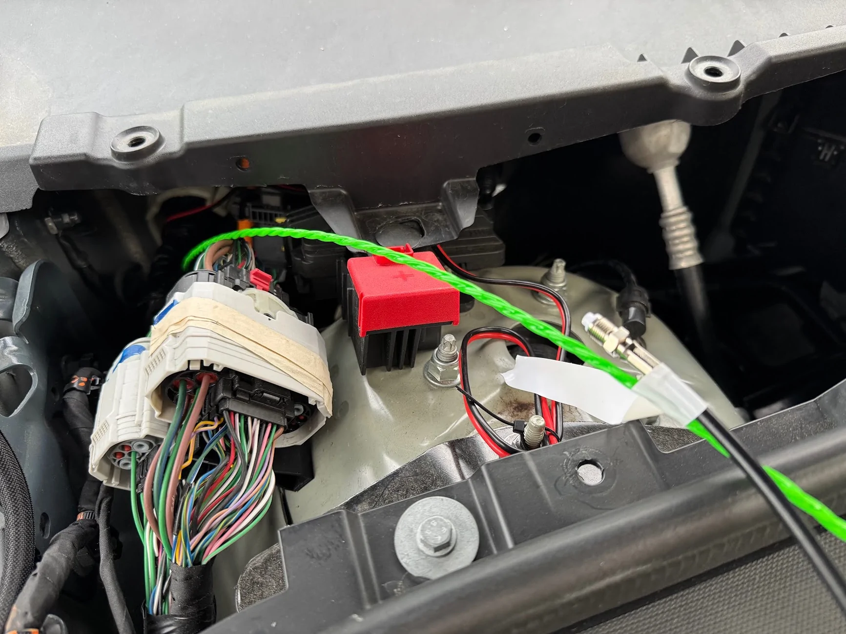
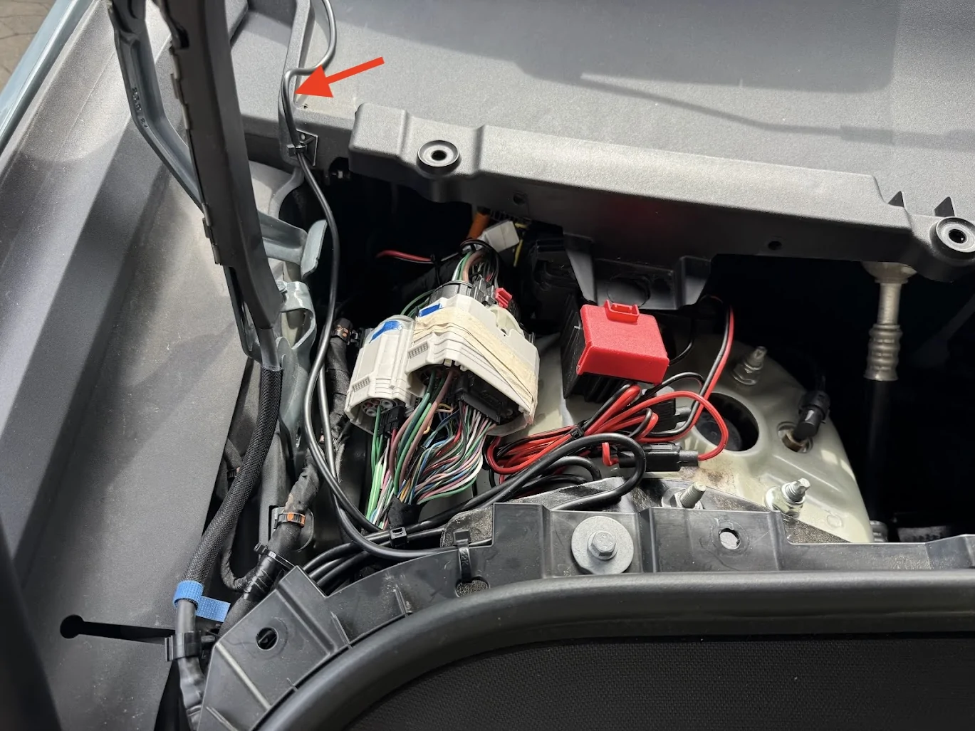
Now, onto connecting the power. The frunk trim removed earlier exposes the 12v jump point that @Joules Burn discovered. Behind the red swing-tab is another cover that is clipped and swings open towards the passengers side, it exposes two 10mm threaded bolts, both carrying 12v DC. The red arrow is 12v, the brown arrow is ground, which is also a 10mm socket bolt. This is where my power cables will tie into:
I needed a small socket wrench with a 10mm socket to get at the 12V nut, but the ground nut is easily accessible. First, I removed the fuses on the wires, which probably wasn't necessary, but habit.
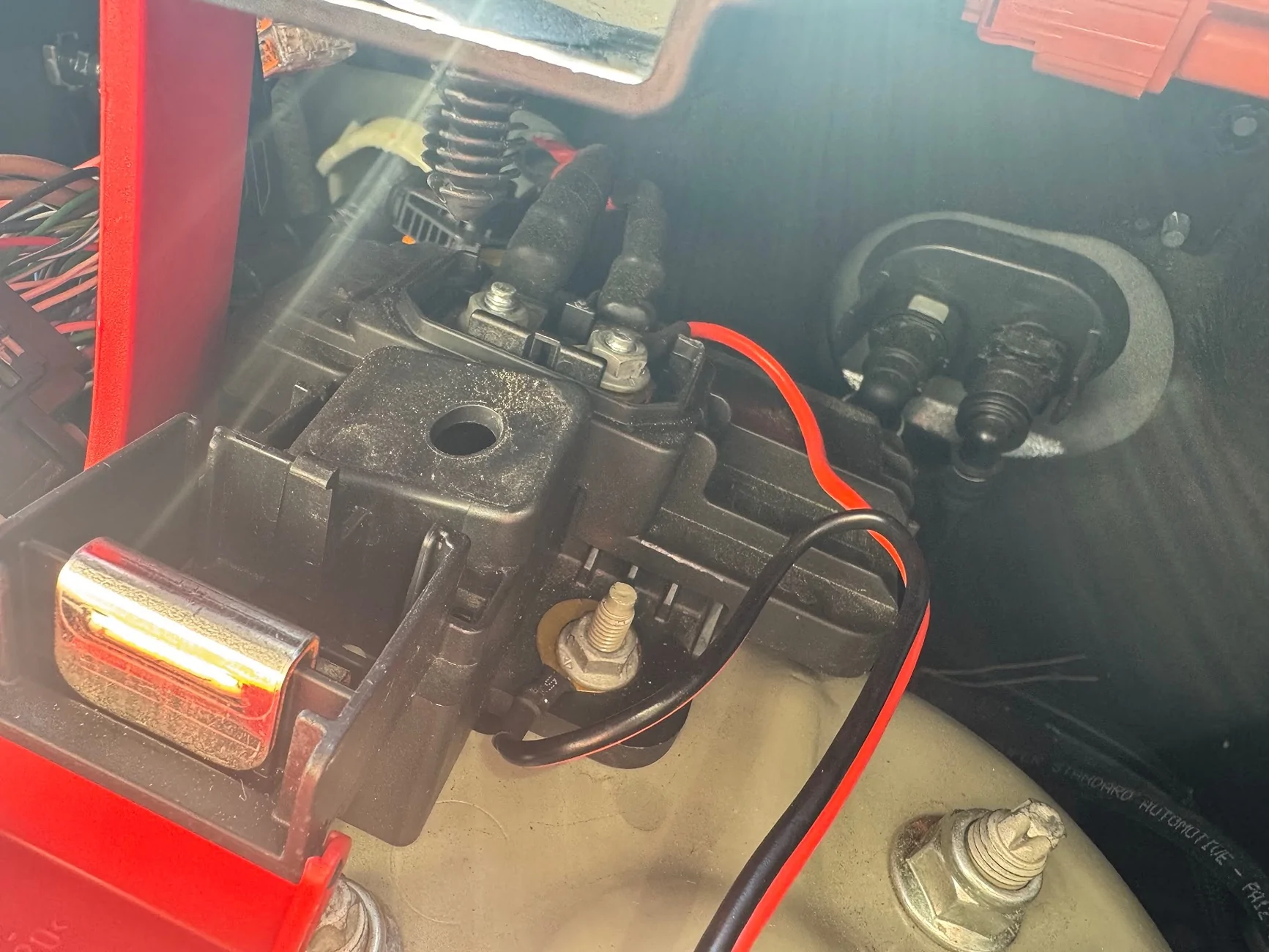
Then, after confirming with a multimeter that the top bolt was getting 13.1v, and the bottom bolt was ground. I unscrewed the nuts and mounted the wires, and tightened the nuts back up. I didn't disconnect the battery or remove anything, just put the new wires ends above any existing ones and cranked down.
I replaced the fuses after connecting the power in the cab to the radio, and confirming it was now working.
Antenna Cable
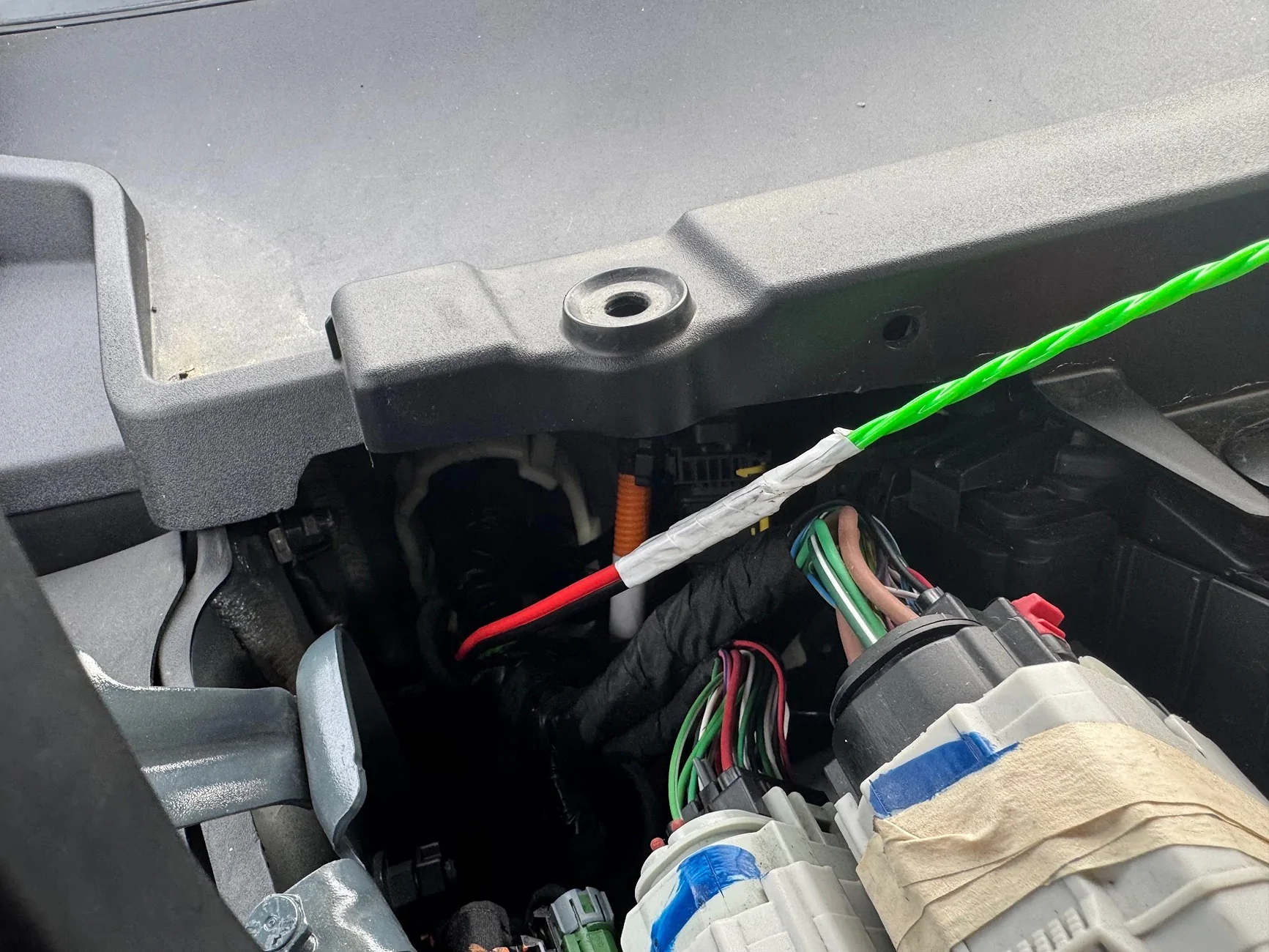
Next, a similar process for the antenna. This time, I fished the fish tape from the engine bay side through the prolapsed nipple into the cab. Then I taped up the antenna connector and pulled it through from the outside in. The other end of the antenna connector is a right-angle 3/8" NMO mount, which wouldn't have passed through the grommet easily.
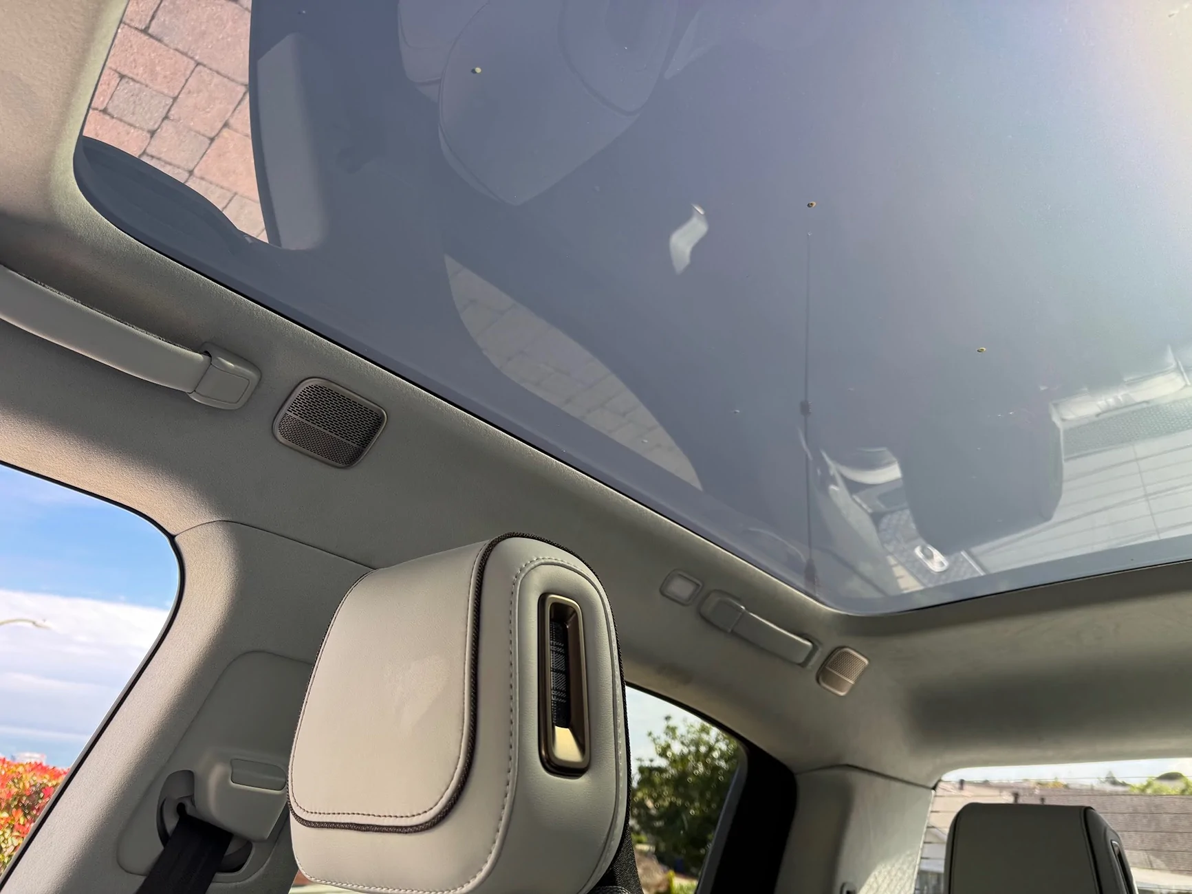
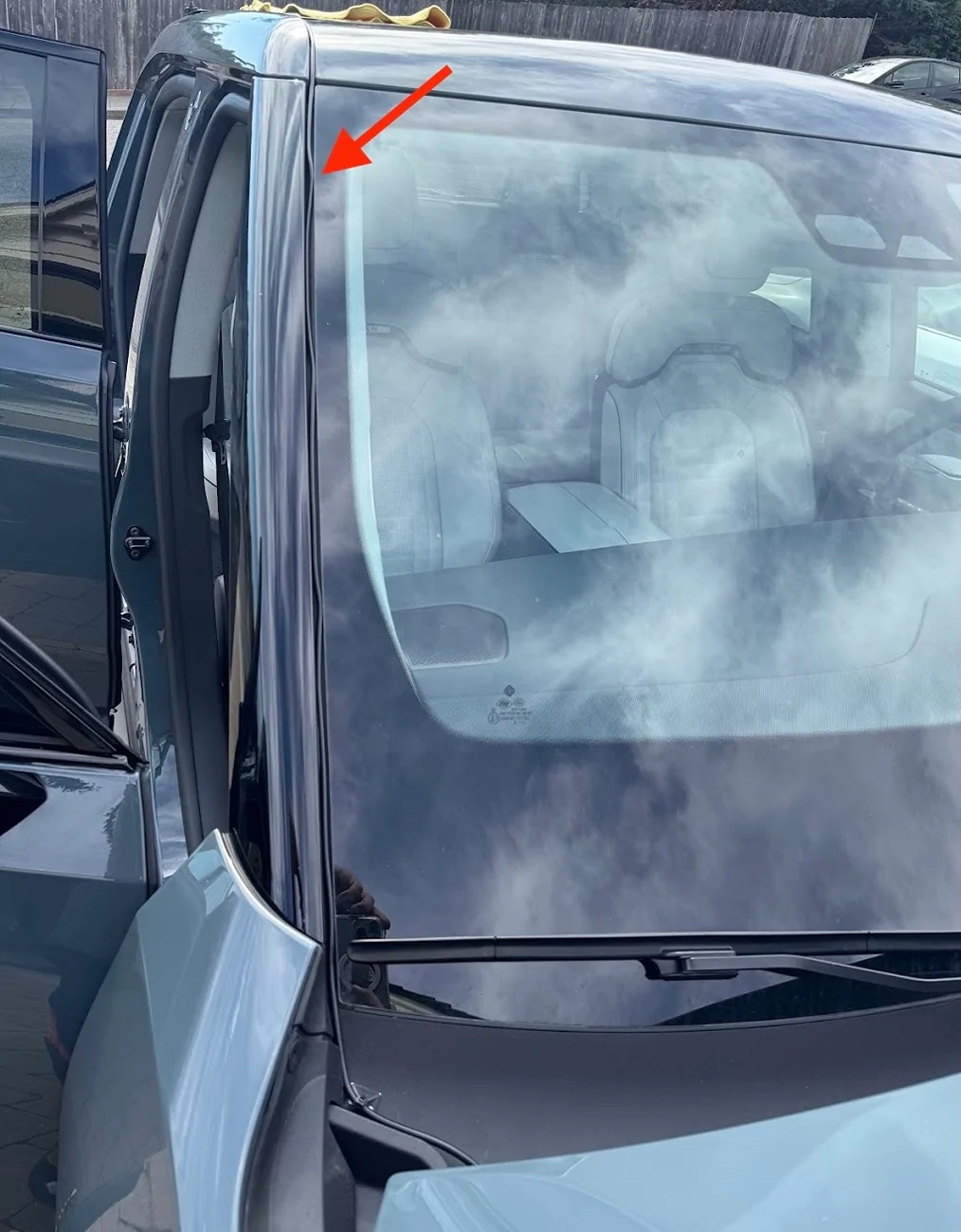
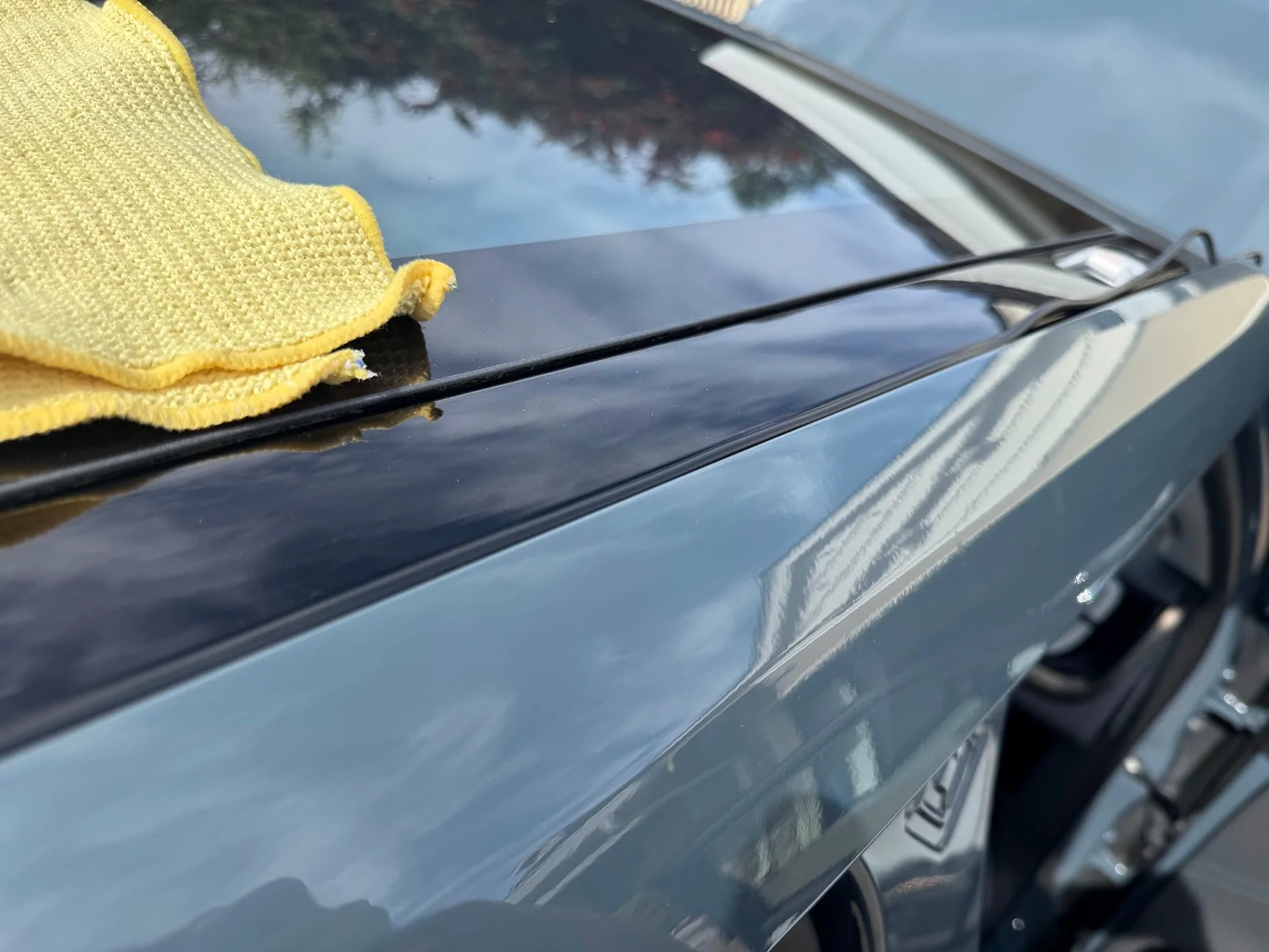
Once I hand enough antenna cable to reach the head unit, I routed the cable up the windshield and along the gap between the top body panel and the cargo rail:

At the bottom of windshield behind the hood, I gave it a bit of upward rise/loop so water wouldn't drip down and follow the cable into the bay.

All of the interior cable routing and securing was done using the adhesive zip tip mounts/pads.
NMO Mount on Crossbar Adapters
This is my FAVORITE part of the build. I didn't want to drill a hole in the bodywork for an antenna, nor did I want to remove more internal panels than necessary to find a way to route the antenna cable from high up on the outside of the truck down into the the lower interior. A ditch-light or hood mount would have probably been the easiest, but I wanted a bit more height and didn't want the antenna visible all the time as I was driving. So I looked into ways to use the cargo crossbar mounts on the top of the truck, which I've never used.
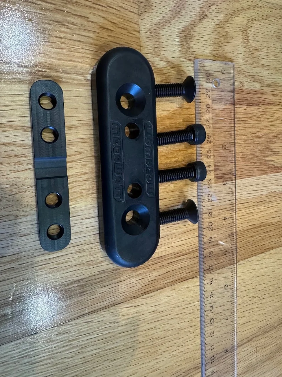
I got a set of adapters from Megawatt that mount to the crossbar eyelets, and attach to things with M8 screws. These things are solid billet steel and about 1 lb each!
A generic bracket that mounts to these adapters and first a 3/8" NMO mount should be pretty easy to find (they are), but I realized that buying them retail was actually more than if I just designed the part I wanted, and had them custom fabricated/cut/painted!
I printed a couple of prototypes, trying to see if wanted to make something that could be a ground plane:
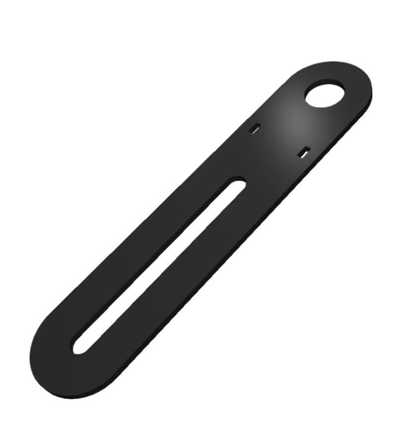
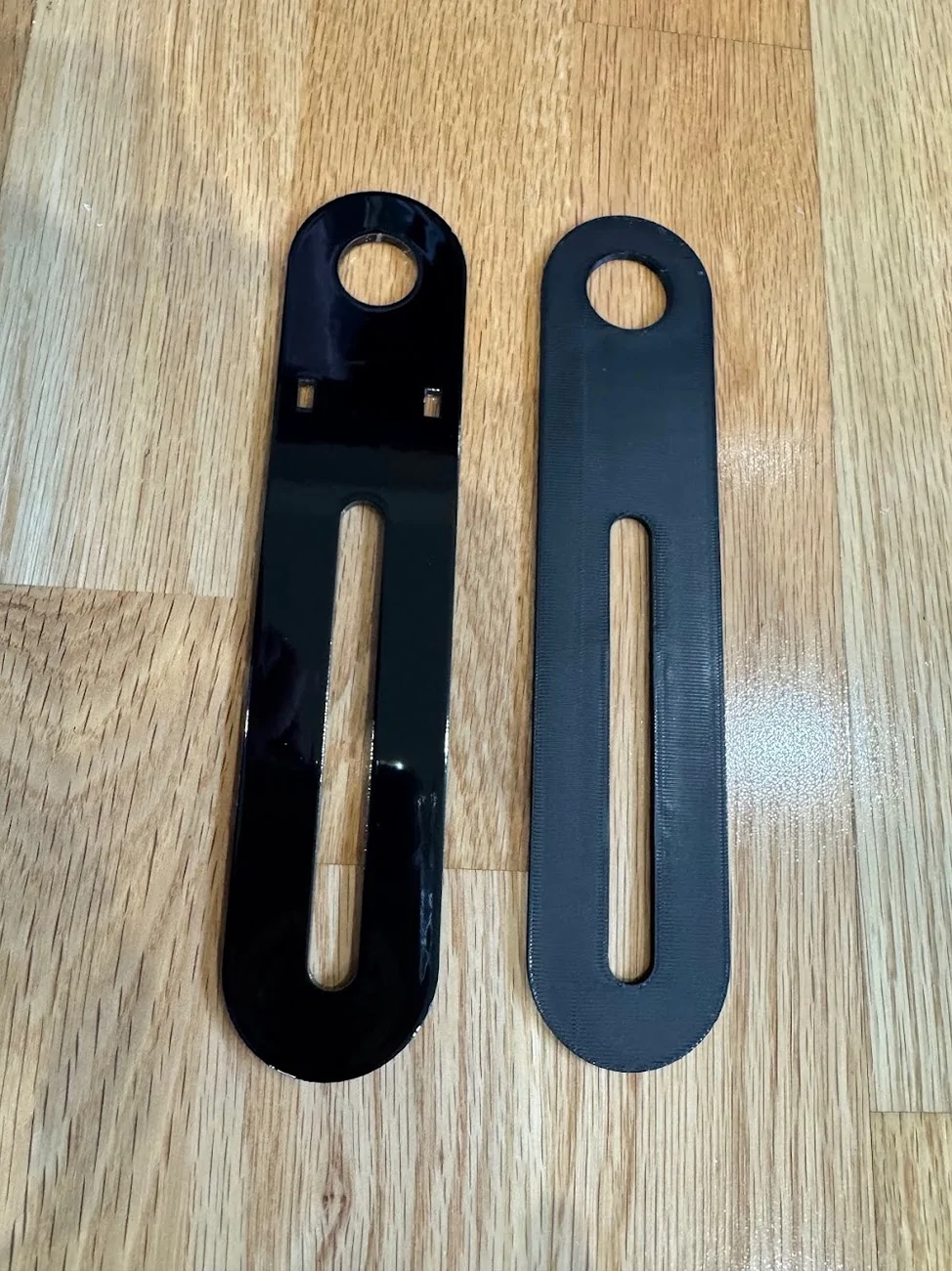
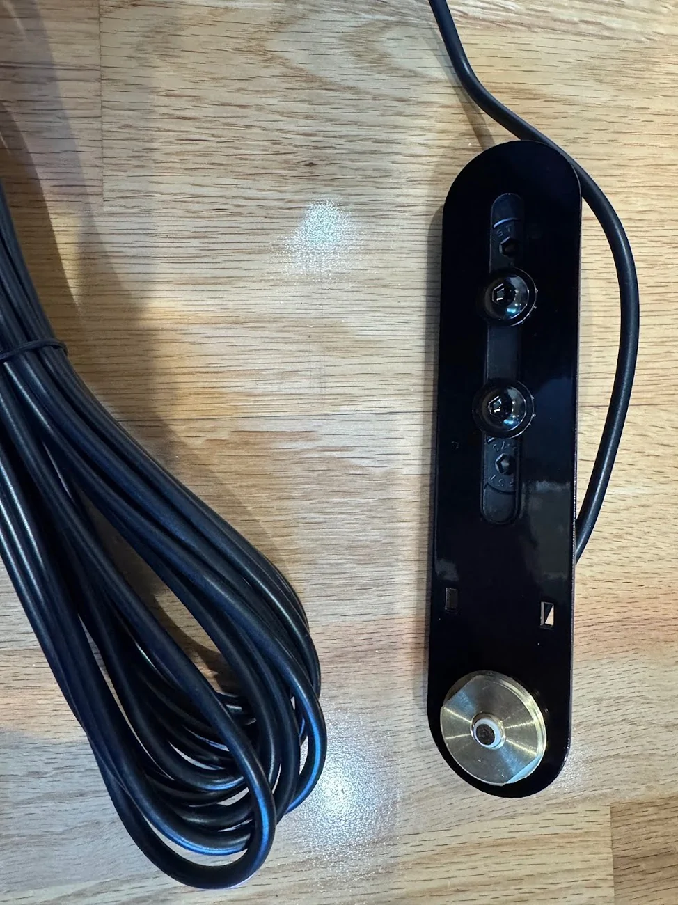
In the end, I stayed simple. A straight bracket, minimalist, forward/backward adjustable, can be used on driver or passenger side, with some holes for zip ties if needed. The design, and my 3D print prototype along with the final in 304 stainless, 0.125" think, powder coated gloss black:


Total for TWO of these sent from SendCutSend.com: $35, cut, deburred, painted. Interestingly, it was cheaper to order two than one, since they effectively have a $35 minimum order size. Still, cheaper than a lot of similar brackets available, and this one is EXACTLY the way I want it!
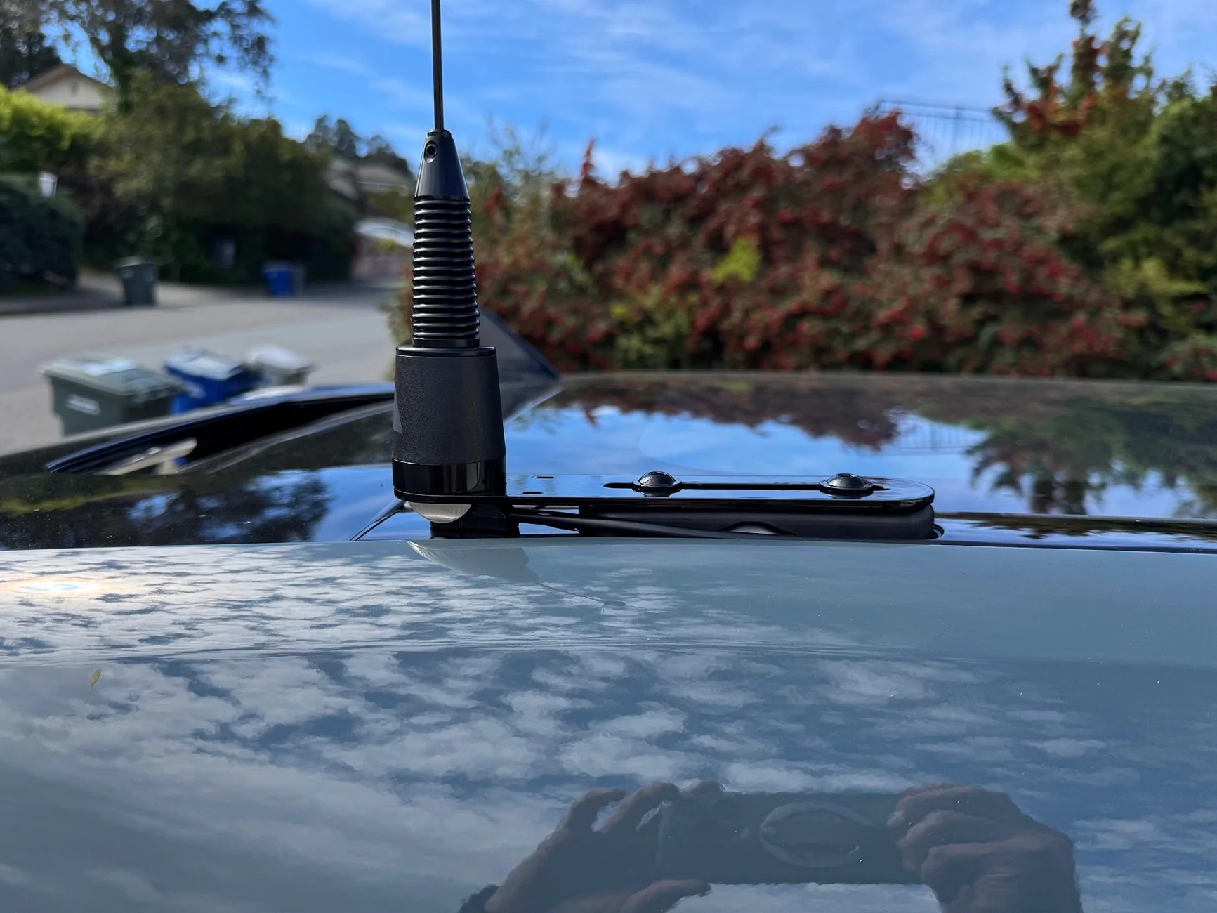
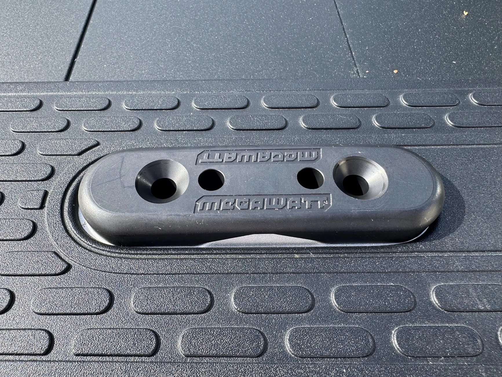
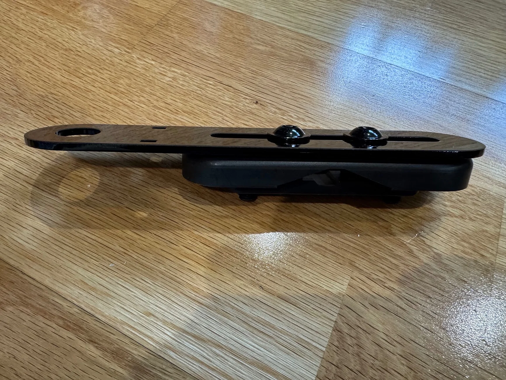
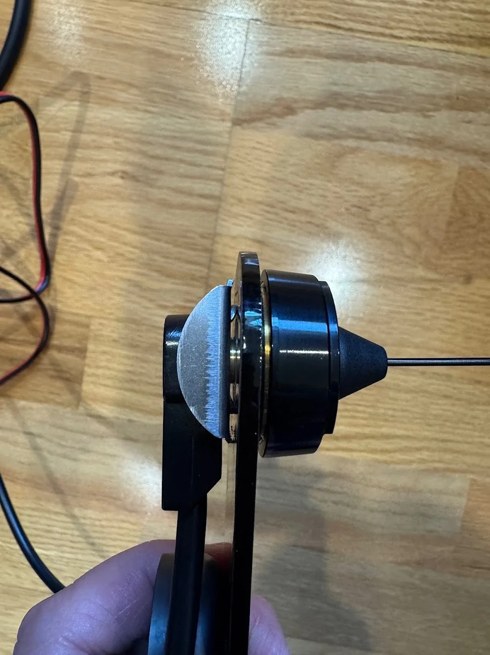
Mounted to the Megawatt:
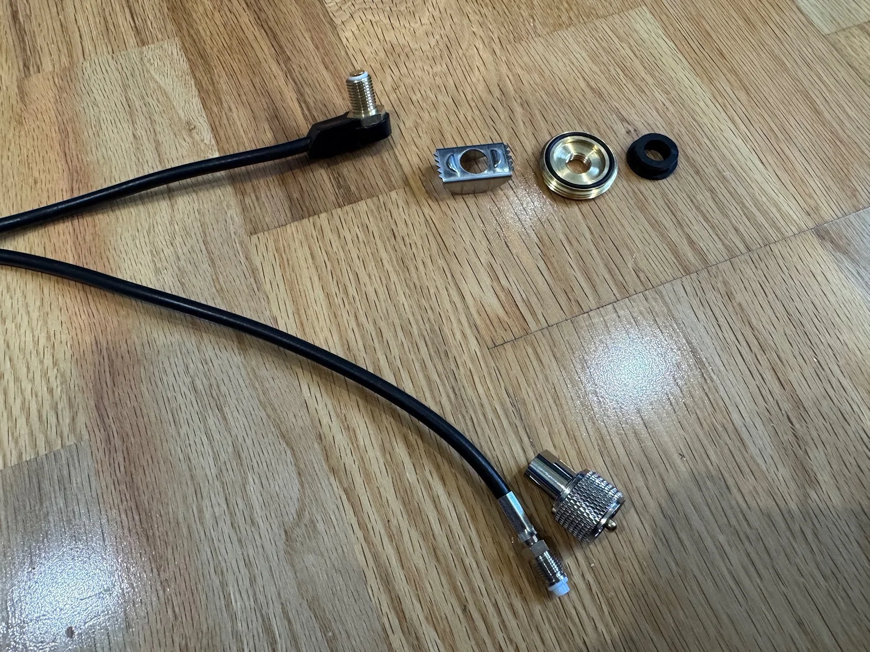
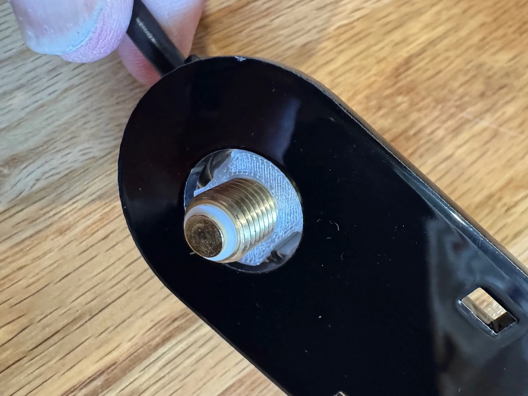
Here's the NMO mount. These things are dumb, or at least Midland's is (the MXTA24). Their official marketing image seems to have it installed wrong, and in reality, all the parts are optional and reversible. The weatherproofing o-ring doesn't really do anything when it's not mounted to a hood/trunk, and the little spacer they provide only seems to work if you are mounting it on something with a particular range of thickness. In the end, I just did what made the most sense, including printing a custom spacer:
I'm actually not sure if the crossbar attachments are connected to vehicle ground, but did add a small ground connector from the antenna, as opposed to scuffing through the powder coating.
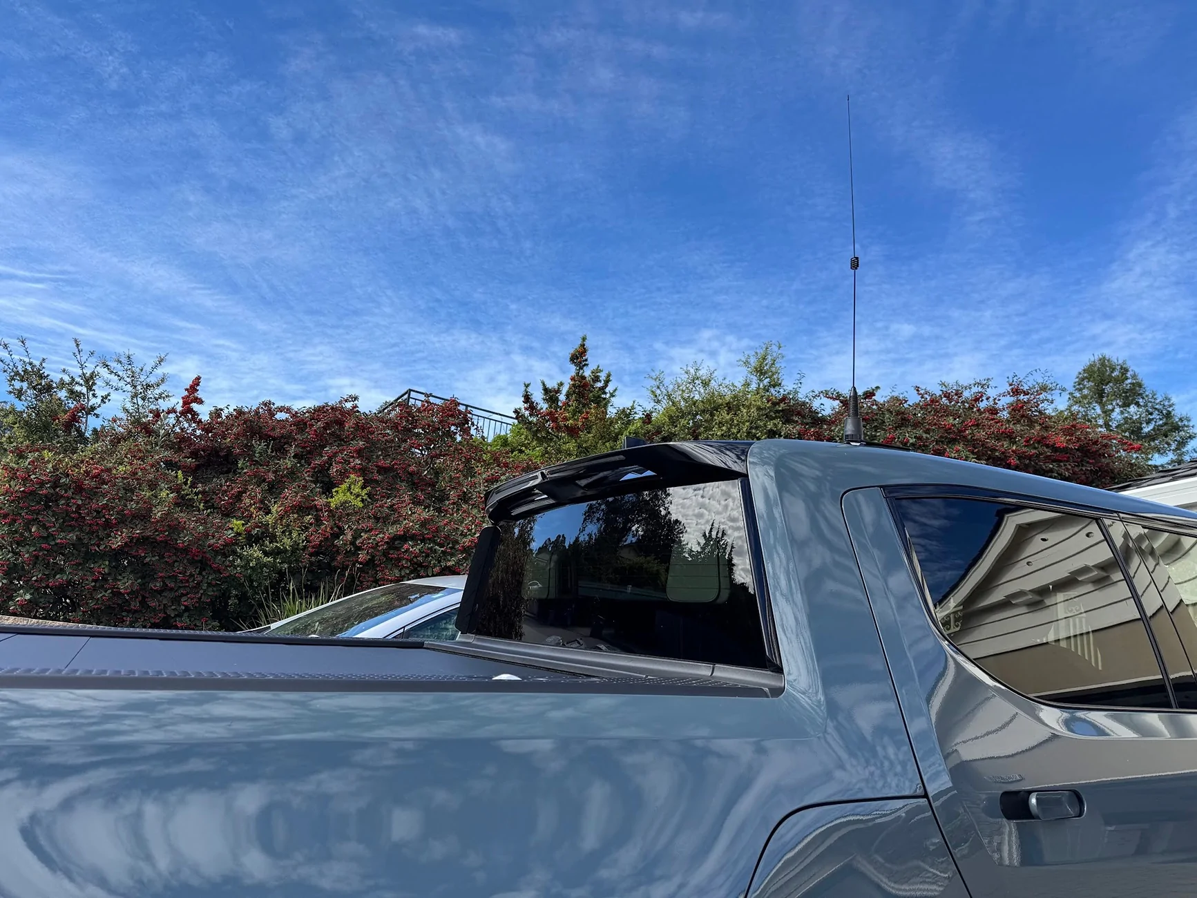
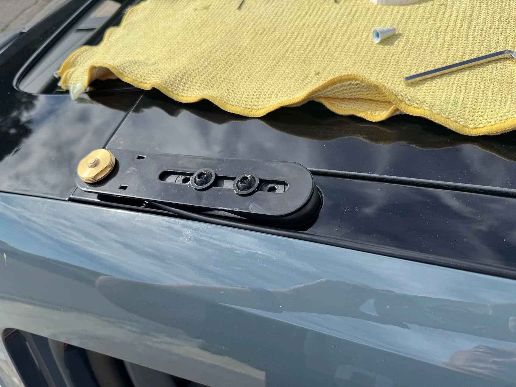
Going back to the cable (I realize this is a bit out of order since I fished the NMO cable already above), here is everything mounted, using the stubby antenna that comes with the MXT575:

I don't think anyone will ever see it, but the glossy powdercoat matches the trim piece so perfectly.
Mic/Control jack
Back to the dashboard. One thing I can't stand is surface-mounted electronics with wires that kind of snake around and then disappear into a seam between two dash panels. So to connect a microphone in a cab to a head unit hidden in the dash, I wanted to use a connector, similar to Ervan's here.
That required cutting into the lower dash that I just removed, and I was very, very nervous about cosmetic damage. Luckily, the panel-mount female RJ45 jack has enough of a lip to hide any reasonable cut mistakes.
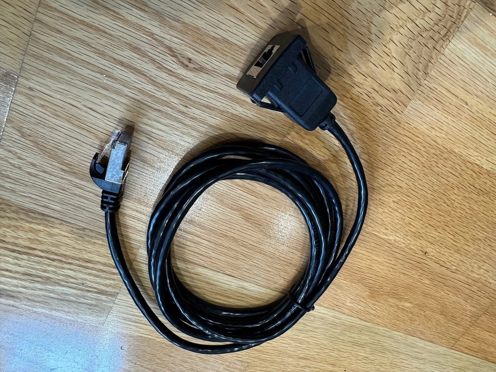
Here's the jack. It has a wide lip, and has 4 built-in clips to firmly hold the jack against whatever you mount it to. Amazon has a 1m and 2m version, the 1m one is plenty long enough (and important in another way, which I'll describe below):
First, where to cut. The dash panel comes really close to the AC hardware, so the best space is right in the middle, which I believe is a gap where the old 12v hardware used to sit:
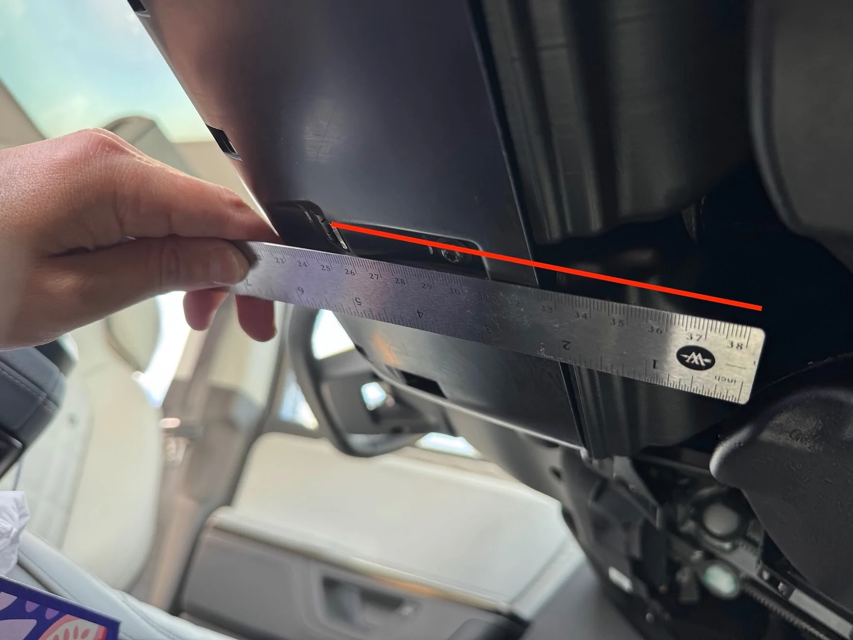
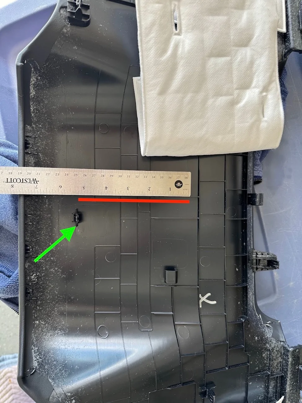
To measure where this is on the panel, I measured from the retaining clip to the gap, which is right at 5.5 inches, give or take. I then measured the same distance on the inside of the panel.
One thing to note: the clips and markings on the plastic are NOT centrered, and I can't for the life of me tell if the AC vents are actually lined up with the center console. In any case, my advice is to line it up centered to the AC vents, and not the center console.
The markings I made on the plastic here to position the hole are incorrect, and I had to adjust after realizing the hole I drilled was off-center. I've tried to correct it with the red box.

Also, the instructions on the adapter say to drill a 20.07mm hole side to side, and a 20.2mm hole top to bottom. That's BS. You can get by with a 21mm hole side to side, but because of the thickness of the clips, you actually need something like 24mm top to bottom. Even then, I ended up using a flathead screwdriver to dig under the clips and pull them out. It's ugly on the inside, but outside, surprisingly flawless and almost OEM-looking! Also, it's in a spot nobody will ever see.
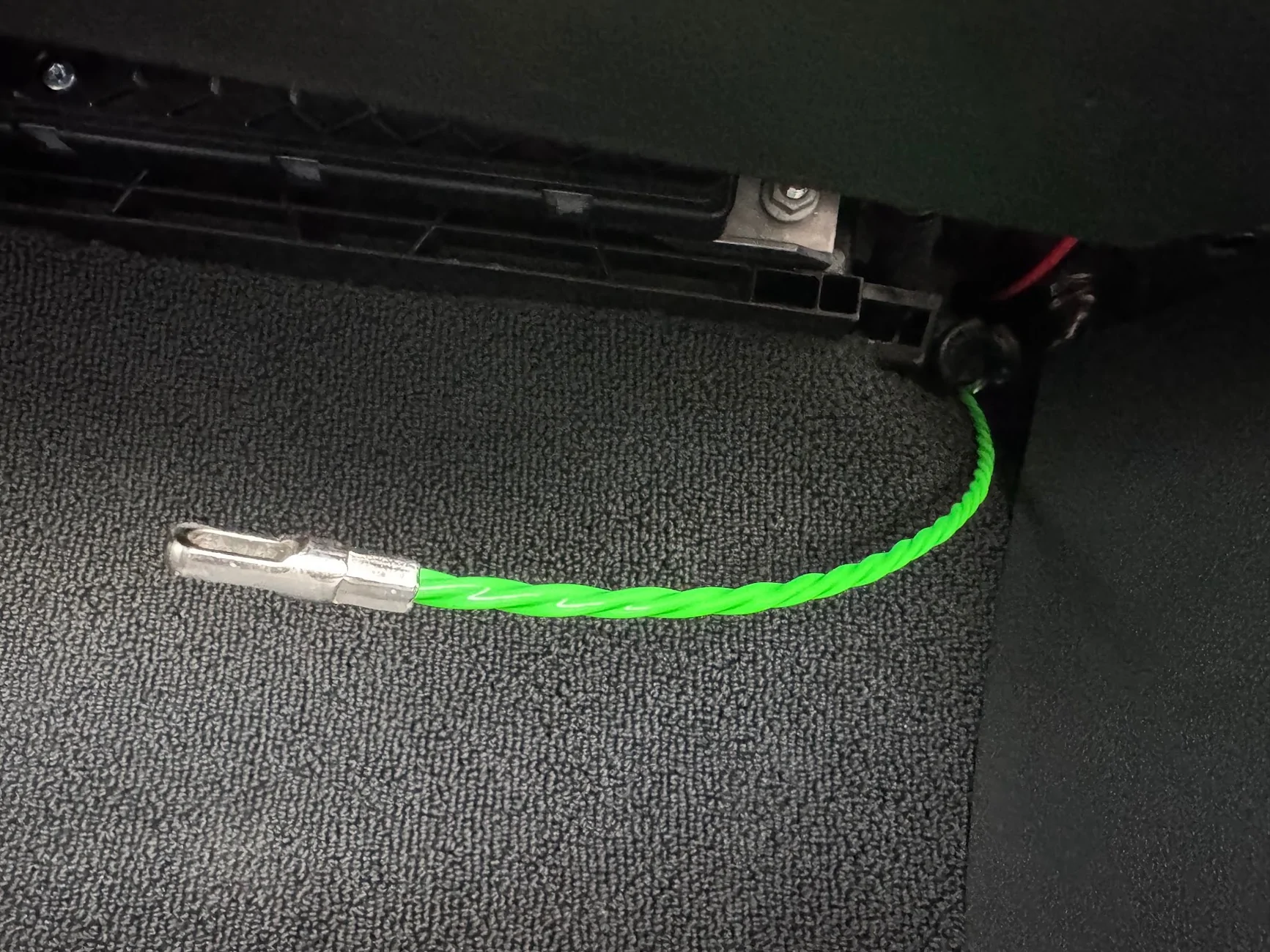
The jack feeds from the outside of the panel to the inside, and the interior cable can be routed to the headunit a few inches away.
One note on the extension RJ45 cables and the MXT575 (and maybe MXT275): Any extension you have will likely introduce noise (clicking and popping) into the espeaker on the mic unit, even though Midland sells their own extension cable. I've tried a dozen different cables, including Cat6 SCC shielded. The only thing that helps is length, the shorter the better. A 0.5ft patch cable is better than a 3ft cable is better than a 50ft cable. This is why you want to get the shortest panel-mount RJ45 extension you can get away with.
The popping only happens on the mic side of the speaker. If you use the built-in speaker on the headunit, no issues no matter how long the extension cable. With my setup, the head unit is loud and clear coming through the dash, I don't need to use the separate microphone.
I've heard the issue is even worse on Midland's optional upgraded mic (the MXMC01). But since the head unit volume is more than enough for me, I might get this and see if it works. There's only so much "db stands for LCD color" and deciphering HF AO, HO AF, HO AO I can tolerate..
Wrap Up
Once everything was set up, I cleaned up any remaining cable, looping and cable-tying as needed. Re-installing the dash panel was a bit challenging, particularly because the center console/AC area has weird, sharp contact points. I found it was easiest to reinstall the sides first, on both passenger and driver sides, so the panel is supported while working on the fidgety middle (you don't have to hold up the whole panel while doing that). Ultimately, the best way to get the middle is to push it forcefully against the top of the center console (with the RIVIAN lettering) until it clips into place. That should position it to align with the AC vents get those seated, along with that pesky center clip.
On writing this up, I suddenly realized that I left a magnet-mount flashlight inside the dash, so I'll be opening up one edge again today to try to find and retrieve that.
Ultimately, I am super happy with how this turned out. And even with the stubby 6" 2.1db included antenna, I was getting 2-3 miles range over very hilly terrain with zero line of sight. And best of all, I didn't break or seriously mar my truck. Total install time was about 5-6 hours, spread across 3 days. I was driving it around without a lower dash and with footwell pieces hanging off for a few days") But now everything is back together and I have nice new functionality. All I need now is to fashion a nice mic mount that is out of the way of the center storage and cupholders,
But now everything is back together and I have nice new functionality. All I need now is to fashion a nice mic mount that is out of the way of the center storage and cupholders,
Summary
I installed a Midland MXT575 50-watt GMRS radio on my 2025 R1T TriMax. TheThe "headless" head-unit is hidden inside the passenger dash, with a microphone/control jack added to the bottom dash where the cab 12v socket used to be included. Power and antenna pass through a grommet in the firewall, where I tapped a 12V power source (directly linked to battery). The antenna cable is tucked along the edge of the windshield/A-pillar up to the roof, where I have a custom bracket holding an NMO mount on the eyelet intended for the Rivian crossbars. My main objectives for this build were reverseability (I can easily move the antenna mount to the back crossbar eyelets if I ever need the roof crossbars) and professional appearance, with minimal exposed cables, no awkward tucking in between trim pieces, etc.
Parts and Supplies
- Midland MXT575 50-Watt radio
- Midland MXTA26 6dbi antenna (usually just stowed in back seat storage, in case I need it)
- Midland MXTA24 low profile 3/8" NMO mount
- Megawatt Crossbar Cargo adapter
- Custom steel bracket to attach NMO to crossbar adapter and support antenna
- CERRXIAN RJ45 Male to Female LAN Ethernet Network Cat 5e Panel Mount Cable (Black)(1m) from Amazon. (no affiliate links)
- Scratchless auto trim removal kit from Amazon. (no affiliate links)
- Zip ties and adhesive zip tie mounts from Amazon (no affiliate links)
- Cable Puller fish tape from Amazon (no affiliate links)
- Wago connectors/wire nuts
- T25 Torx bit to remove footwell trim on driver/pasenger sides
- 10mm socket, with small socket wrench, for the 12v taps under the hood
- Drill, utility knife, wire strippers, velcro
- 3D Printer for prototyping
I first considered whether to install the headunit in the frunk/engine bay, in the gear tunnel, in the rear seat storage, or inside the dash. Each had its own complications and wiring/routing challenges. Ultimately I decided to put it in the dash, and route power and antenna cables to the engine bay. Here's the overview pic. Front passenger footwell looking up towards the front of the truck. The red square is where the headunit is tucked. The red circle is where the RJ45 female port is installed for the mic. The green circle is the location of the grommet to fish cables from:
First, I removed the lower passenger footwell panel. There are 5 clips that just pull/pry out, no screws on this side.
The flexible panel cradled by the U is the passenger knee airbag. Do not touch or mess with that in any way.
This exposes two T-25 torx-bit screws that I needed to remove in order to remove the full-length under-dash panel that spans the driver and passenger sides. The first pic is one near the center console, the second is near the passenger side door:
While I was at it, I had to do the driver side too. NOTE that on my car, the driver side has two additional T-25 torx screws that had to be removed first. So this makes for a total of 6 torx screws between driver and passenger side. The driver side is actually two pieces. The small piece above the accelerator will come right off. The clutch side just needs to be loosened to access the hidden torx screw (just like on the passenger side):
Before removing the under-dash panel, I had to pop and loosen the small side panel that is exposed when the the front door is open. The lowest two clips anchor the dash piece; I didn't need to remove the entire side panel:
I had to do the same on the driver side to get the full panel off, which is needed to cut the hole for the mic adapter. I started pulling the panel down by releasing the clips:
Here are the clip locations. The center area is by far the most troublesome. The green clip took a LOT of force to remove, and it pulled a metal barb out of the retaining clip that I had to reseat. The two protrusions at the bottom need to be sandwiched to the center console back (the piece with the big RIVIAN letters on it). The AC vent shroud area at the top has to be carefully removed from the vents, which have all kinds of sharp shark-teeth that will scratch and cut the faux leather.
Once the panel is off, this is what I was left with:
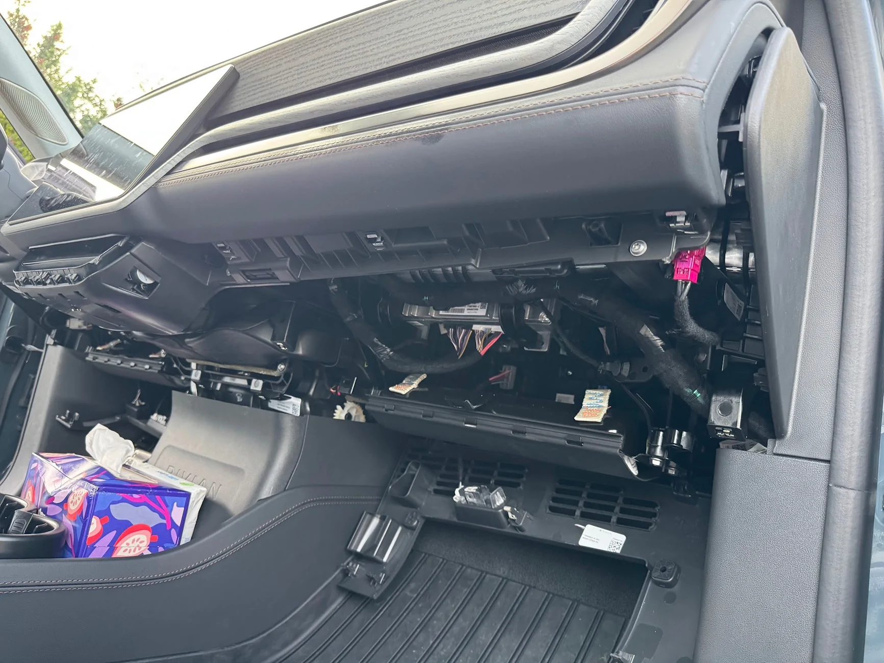
There are a few mounting positions available. The MXT575 is a big unit, and some of the smaller ones can fit almost anywhere. I followed Sulley's approach and placed in the passenger dash closer to the center display, on a ledge/perch that it can stand up sideways on, and it's safely sandwiched between support members, with the mic facing outward. Here's a picture from the bottom of the passenger footwell by the door, looking up towards the driver-side ceiling. The radio headunit is in green.
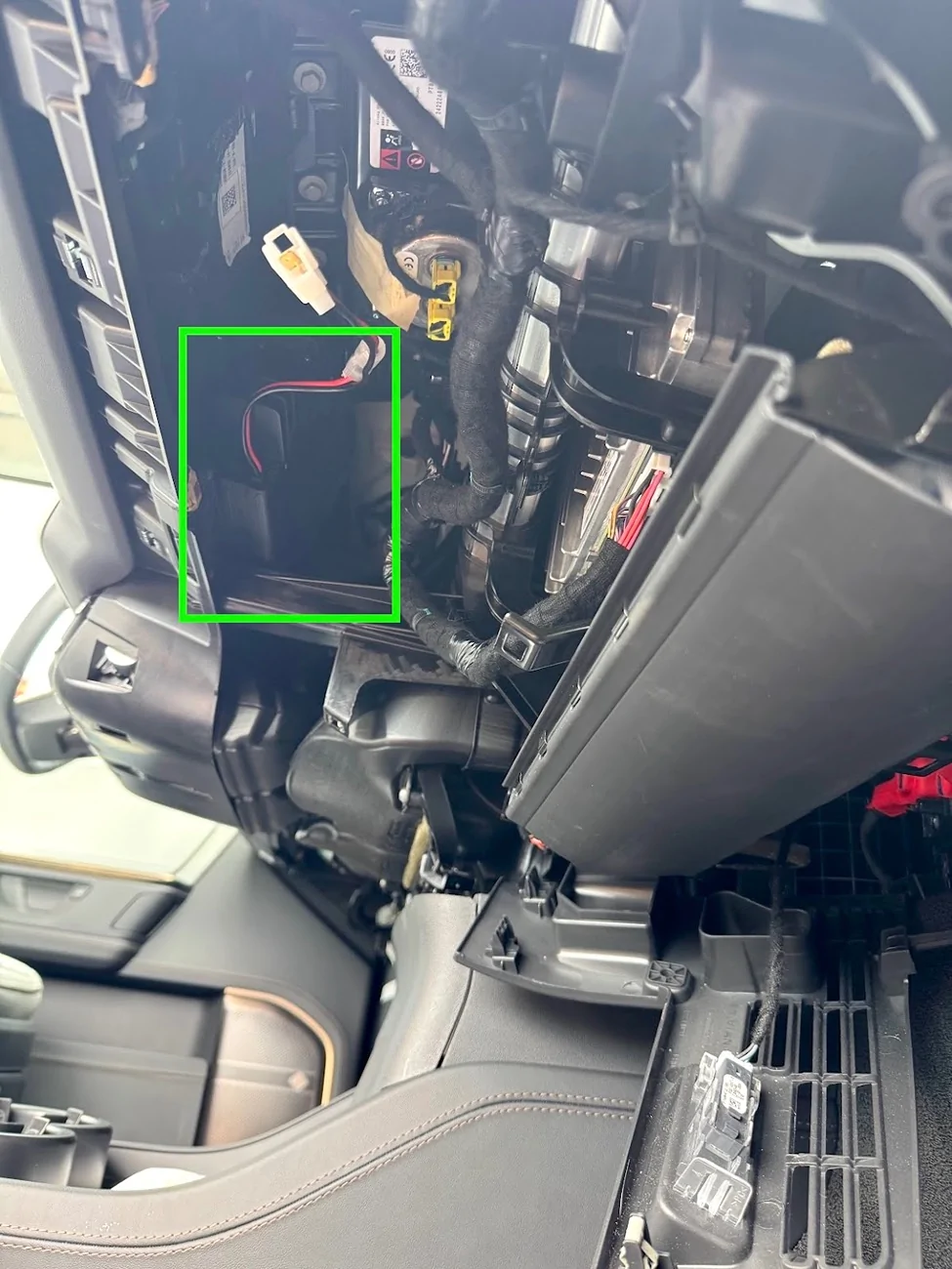
I used industrial-strength velcro and zip ties to keep the head-unit there. Hopefully it'll be stable enough. One thing's for sure, it's super loud even at volume 3-10 in this location.
12V Power Cable
Moving on to power and cable routing next. First, I popped off the trim piece at the back of the frunk, it just comes right off with a few clips:

First, the grommet. A closeup of the above picture shows the two exposed/unused nipples that can be cut/pierce to pull wire through:
Here it is from inside the cab, at the back of the passenger footwell near the door hinge side. It's a fit for a hand, so I'm using a screwdriver to just puncture the nipple from the inside. Hint - use grease/lubricant, the grommet is very tacky/sticky rubber.
Unlike others have found, on my car the grommet is VERY stretchy, it's like a thick balloon. I had to use a longer screwdriver to puncture it, and when pulling the screwdriver out, it pulled the nipple and er....prolapsed it. Which is actually great, because the antenna has to be fished from the outside in, and for me, the power from the inside out, so having one nipple outward facing and one inward facing worked out great. Here you can see from the engine bay, the flathead screwdriver breaking through the grommet:
I used a bit of grease on the grommet, then stuck a fish tape wire from the inside and just pushed it through:
The power cable for the radio has all kinds of weird connector ends, as well as fuses in the middle, so I had to cut it to fish through the grommet.
I taped the segment of the power cable to the inside and just kept fishing the wire through. Once I got the power cable through, I just removed the tape and pulled out the fish tape.
Once through, I reconnected the two segments of the power cord with a WAGO lever nut for each of the 12v and ground wires. I used 3-lever WAGOs in case I ever wanted to tap more 12v power (e.g., frunk outlet). I also packed the wagos with waterproof grease and wrapped them in electrical tape, then zip-tied them face-up so any water runs down them and not into them. LMK if I'm going to burn down the car.
Now, onto connecting the power. The frunk trim removed earlier exposes the 12v jump point that @Joules Burn discovered. Behind the red swing-tab is another cover that is clipped and swings open towards the passengers side, it exposes two 10mm threaded bolts, both carrying 12v DC. The red arrow is 12v, the brown arrow is ground, which is also a 10mm socket bolt. This is where my power cables will tie into:
I needed a small socket wrench with a 10mm socket to get at the 12V nut, but the ground nut is easily accessible. First, I removed the fuses on the wires, which probably wasn't necessary, but habit.
Then, after confirming with a multimeter that the top bolt was getting 13.1v, and the bottom bolt was ground. I unscrewed the nuts and mounted the wires, and tightened the nuts back up. I didn't disconnect the battery or remove anything, just put the new wires ends above any existing ones and cranked down.
I replaced the fuses after connecting the power in the cab to the radio, and confirming it was now working.
Antenna Cable
Next, a similar process for the antenna. This time, I fished the fish tape from the engine bay side through the prolapsed nipple into the cab. Then I taped up the antenna connector and pulled it through from the outside in. The other end of the antenna connector is a right-angle 3/8" NMO mount, which wouldn't have passed through the grommet easily.
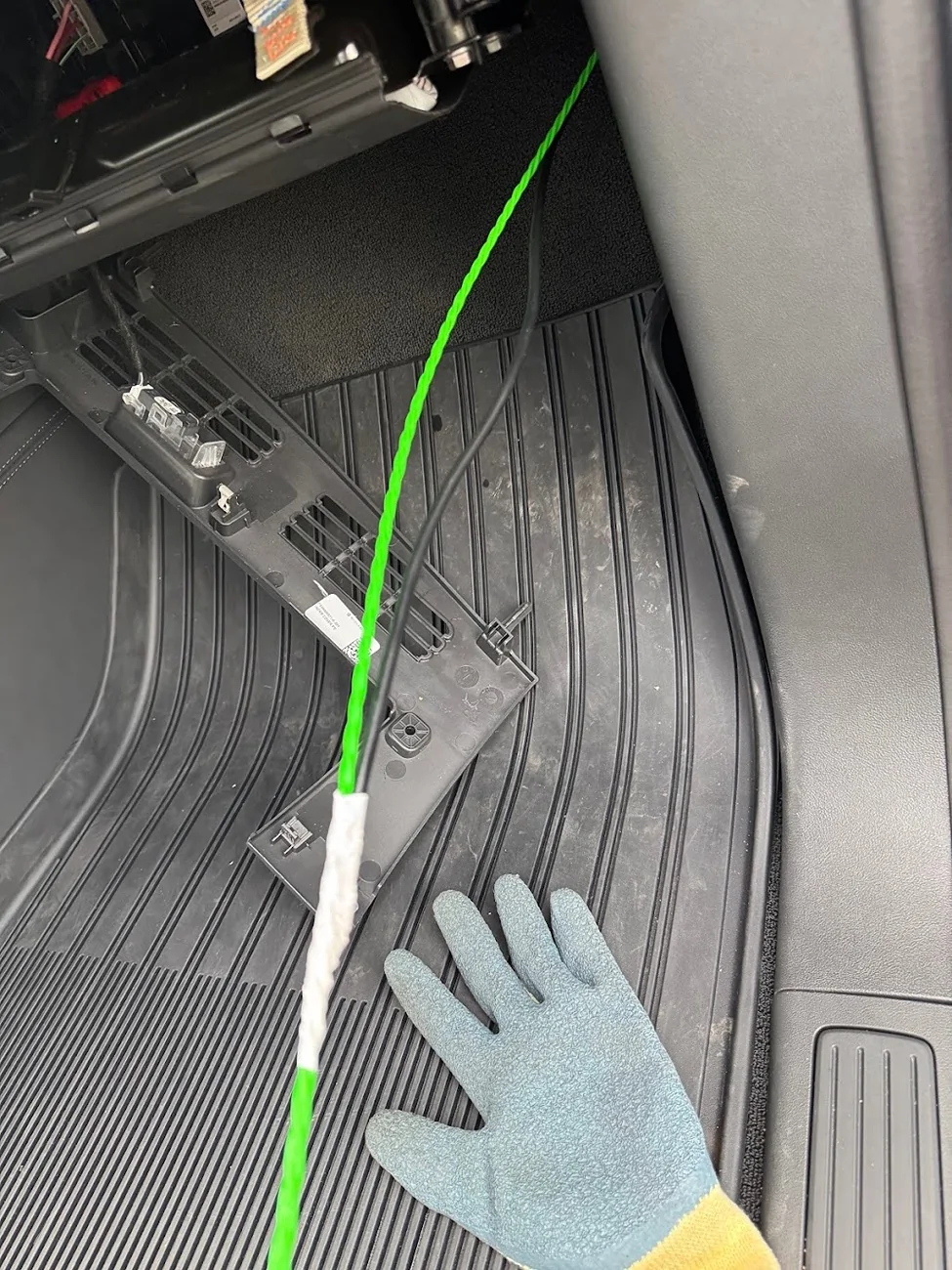
Once I hand enough antenna cable to reach the head unit, I routed the cable up the windshield and along the gap between the top body panel and the cargo rail:
At the bottom of windshield behind the hood, I gave it a bit of upward rise/loop so water wouldn't drip down and follow the cable into the bay.
All of the interior cable routing and securing was done using the adhesive zip tip mounts/pads.
NMO Mount on Crossbar Adapters
This is my FAVORITE part of the build. I didn't want to drill a hole in the bodywork for an antenna, nor did I want to remove more internal panels than necessary to find a way to route the antenna cable from high up on the outside of the truck down into the the lower interior. A ditch-light or hood mount would have probably been the easiest, but I wanted a bit more height and didn't want the antenna visible all the time as I was driving. So I looked into ways to use the cargo crossbar mounts on the top of the truck, which I've never used.
I got a set of adapters from Megawatt that mount to the crossbar eyelets, and attach to things with M8 screws. These things are solid billet steel and about 1 lb each!
A generic bracket that mounts to these adapters and first a 3/8" NMO mount should be pretty easy to find (they are), but I realized that buying them retail was actually more than if I just designed the part I wanted, and had them custom fabricated/cut/painted!
I printed a couple of prototypes, trying to see if wanted to make something that could be a ground plane:
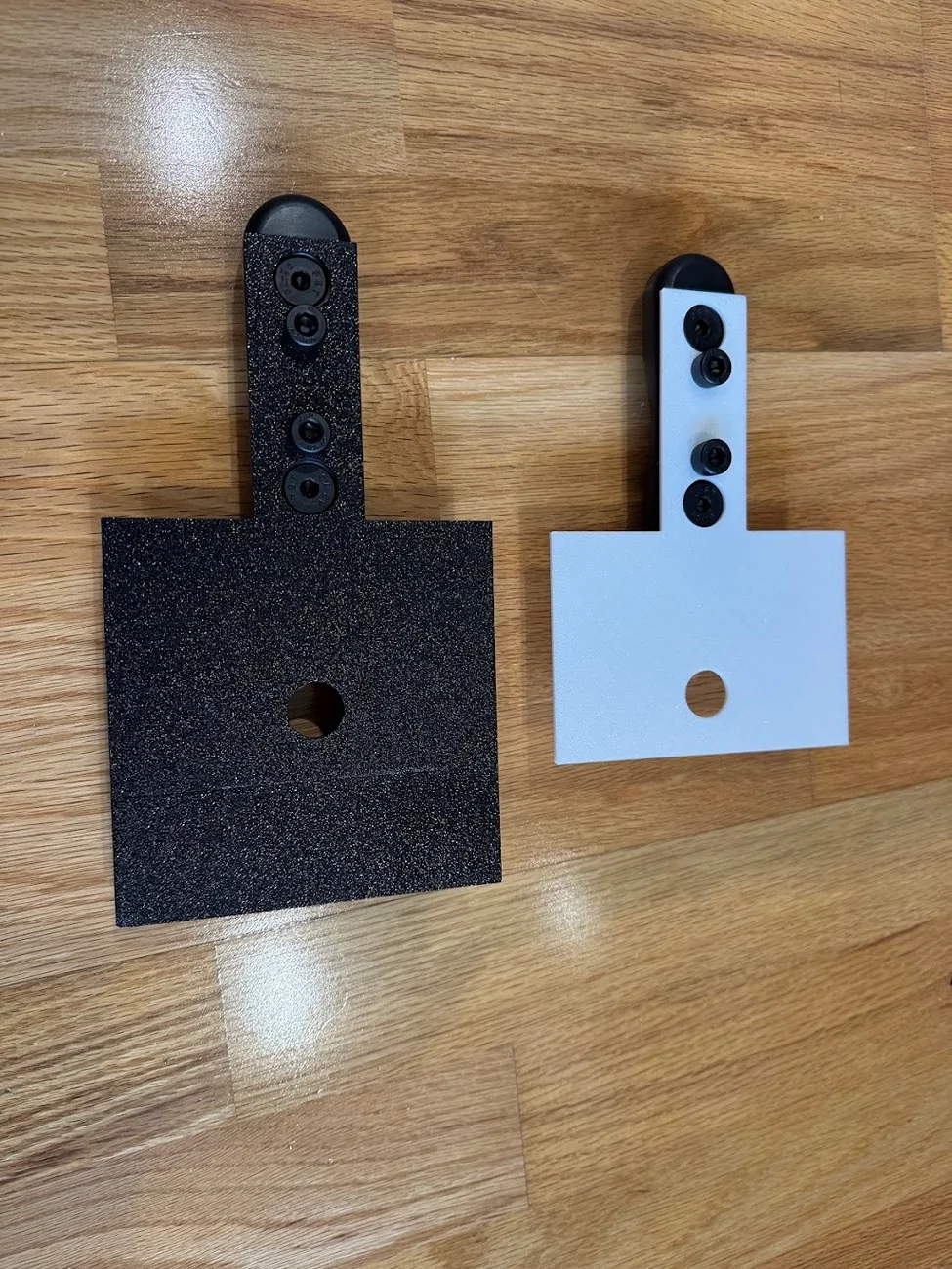
In the end, I stayed simple. A straight bracket, minimalist, forward/backward adjustable, can be used on driver or passenger side, with some holes for zip ties if needed. The design, and my 3D print prototype along with the final in 304 stainless, 0.125" think, powder coated gloss black:

Total for TWO of these sent from SendCutSend.com: $35, cut, deburred, painted. Interestingly, it was cheaper to order two than one, since they effectively have a $35 minimum order size. Still, cheaper than a lot of similar brackets available, and this one is EXACTLY the way I want it!
Mounted to the Megawatt:
Here's the NMO mount. These things are dumb, or at least Midland's is (the MXTA24). Their official marketing image seems to have it installed wrong, and in reality, all the parts are optional and reversible. The weatherproofing o-ring doesn't really do anything when it's not mounted to a hood/trunk, and the little spacer they provide only seems to work if you are mounting it on something with a particular range of thickness. In the end, I just did what made the most sense, including printing a custom spacer:
I'm actually not sure if the crossbar attachments are connected to vehicle ground, but did add a small ground connector from the antenna, as opposed to scuffing through the powder coating.
Going back to the cable (I realize this is a bit out of order since I fished the NMO cable already above), here is everything mounted, using the stubby antenna that comes with the MXT575:
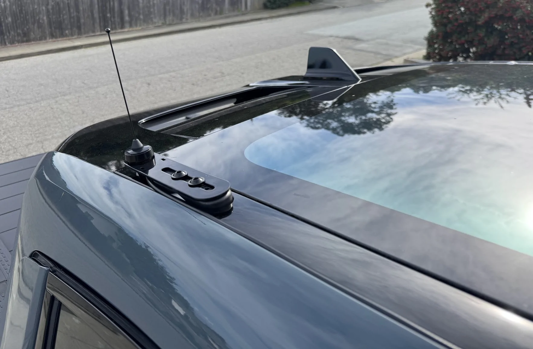
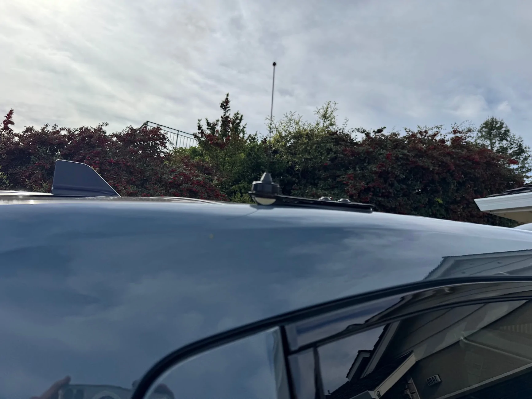
I don't think anyone will ever see it, but the glossy powdercoat matches the trim piece so perfectly.
Mic/Control jack
Back to the dashboard. One thing I can't stand is surface-mounted electronics with wires that kind of snake around and then disappear into a seam between two dash panels. So to connect a microphone in a cab to a head unit hidden in the dash, I wanted to use a connector, similar to Ervan's here.
That required cutting into the lower dash that I just removed, and I was very, very nervous about cosmetic damage. Luckily, the panel-mount female RJ45 jack has enough of a lip to hide any reasonable cut mistakes.
Here's the jack. It has a wide lip, and has 4 built-in clips to firmly hold the jack against whatever you mount it to. Amazon has a 1m and 2m version, the 1m one is plenty long enough (and important in another way, which I'll describe below):
First, where to cut. The dash panel comes really close to the AC hardware, so the best space is right in the middle, which I believe is a gap where the old 12v hardware used to sit:

To measure where this is on the panel, I measured from the retaining clip to the gap, which is right at 5.5 inches, give or take. I then measured the same distance on the inside of the panel.
One thing to note: the clips and markings on the plastic are NOT centrered, and I can't for the life of me tell if the AC vents are actually lined up with the center console. In any case, my advice is to line it up centered to the AC vents, and not the center console.
The markings I made on the plastic here to position the hole are incorrect, and I had to adjust after realizing the hole I drilled was off-center. I've tried to correct it with the red box.
Also, the instructions on the adapter say to drill a 20.07mm hole side to side, and a 20.2mm hole top to bottom. That's BS. You can get by with a 21mm hole side to side, but because of the thickness of the clips, you actually need something like 24mm top to bottom. Even then, I ended up using a flathead screwdriver to dig under the clips and pull them out. It's ugly on the inside, but outside, surprisingly flawless and almost OEM-looking! Also, it's in a spot nobody will ever see.
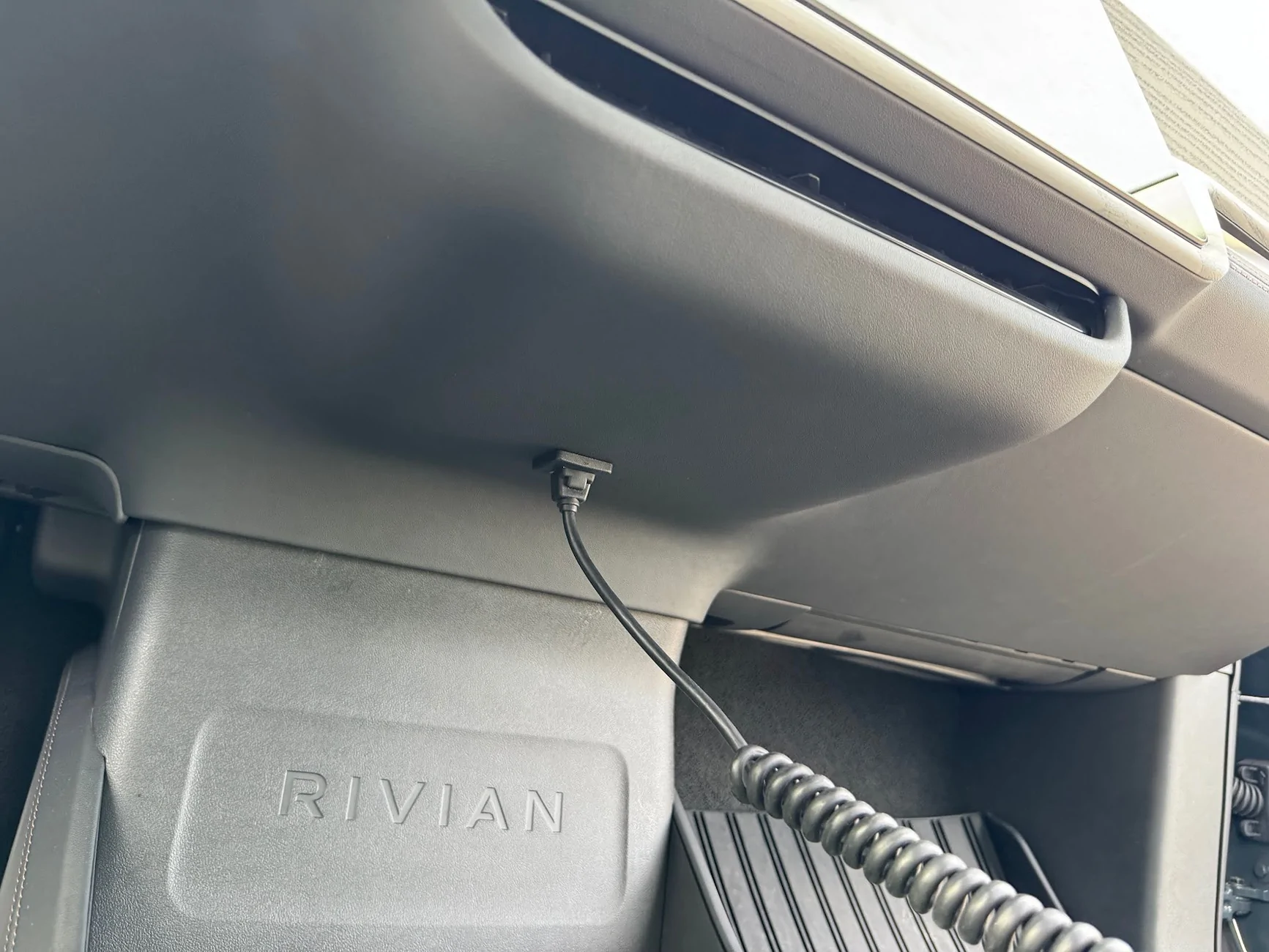
The jack feeds from the outside of the panel to the inside, and the interior cable can be routed to the headunit a few inches away.
One note on the extension RJ45 cables and the MXT575 (and maybe MXT275): Any extension you have will likely introduce noise (clicking and popping) into the espeaker on the mic unit, even though Midland sells their own extension cable. I've tried a dozen different cables, including Cat6 SCC shielded. The only thing that helps is length, the shorter the better. A 0.5ft patch cable is better than a 3ft cable is better than a 50ft cable. This is why you want to get the shortest panel-mount RJ45 extension you can get away with.
The popping only happens on the mic side of the speaker. If you use the built-in speaker on the headunit, no issues no matter how long the extension cable. With my setup, the head unit is loud and clear coming through the dash, I don't need to use the separate microphone.
I've heard the issue is even worse on Midland's optional upgraded mic (the MXMC01). But since the head unit volume is more than enough for me, I might get this and see if it works. There's only so much "db stands for LCD color" and deciphering HF AO, HO AF, HO AO I can tolerate..
Wrap Up
Once everything was set up, I cleaned up any remaining cable, looping and cable-tying as needed. Re-installing the dash panel was a bit challenging, particularly because the center console/AC area has weird, sharp contact points. I found it was easiest to reinstall the sides first, on both passenger and driver sides, so the panel is supported while working on the fidgety middle (you don't have to hold up the whole panel while doing that). Ultimately, the best way to get the middle is to push it forcefully against the top of the center console (with the RIVIAN lettering) until it clips into place. That should position it to align with the AC vents get those seated, along with that pesky center clip.
On writing this up, I suddenly realized that I left a magnet-mount flashlight inside the dash, so I'll be opening up one edge again today to try to find and retrieve that.
Ultimately, I am super happy with how this turned out. And even with the stubby 6" 2.1db included antenna, I was getting 2-3 miles range over very hilly terrain with zero line of sight. And best of all, I didn't break or seriously mar my truck. Total install time was about 5-6 hours, spread across 3 days. I was driving it around without a lower dash and with footwell pieces hanging off for a few days
But now everything is back together and I have nice new functionality. All I need now is to fashion a nice mic mount that is out of the way of the center storage and cupholders,Sponsored
Last edited: